
2600B System SourceMeter SMU Instruments
The source and measurement accuracies are specified at the SourceMeter CHANNEL A (2601B, 2602B, and 2604B) or SourceMeter CHANNEL B (2602B and 2604B) terminals under the following conditions: 1. 23 °C ± 5 °C, <70% relative humidity 2. After 2 hour warm-up 3. Speed normal (1 NPLC) 4. A/D auto-zero enabled 5.
Download 2600B System SourceMeter SMU Instruments

Information
Domain:
Source:
Link to this page:
Documents from same domain

P5200A Series High Voltage Differential Probes ...
download.tek.comHigh Voltage Differential Probes Installation and Safety Instructions & Product Documentation CD ZZZ *P071288902* 071-2889-02. ... To disconnect the probes, first disconnect the probe from the circuit. Next, turn ... P5200A Series High Voltage Differential. P5200A.
TDP0500 & TDP1000 High Voltage Differential Probes ...
download.tek.comWarranty Tektronix warrants that this product will be free from defects in materials and workmanship for a period of one (1) year from the date of

Analyzing 26-53 GBaud PAM4 Optical and Electrical Signals
download.tek.comWWW.TEK.COM | 7 Analyzing 26-53 GBaud PAM4 Optical and Electrical Signals APPICATIO OTE 3. Debugging PAM4 Systems and Transceivers Testing a transceiver for compliance to the specified

Understanding and Performing MIPI D-PHY Physical Layer ...
download.tek.comfrom a miniature circuit, the probes with a wide range of accessories like miniature tips, micro clips, solder-tips, etc are needed. For example, a P7360 probe with square pin adapter, and a probe-tip of P6780 (Partnumber 020-3035-00, kit of 15 …
(Courtesy of Tektronix)
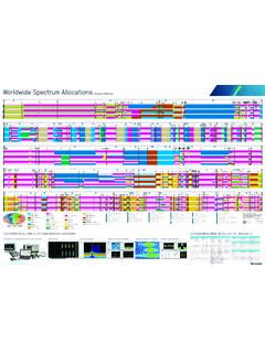
download.tek.comCELLULAR NETWORKS GENERATION TECHNOLOGY CHANNEL SPACING COMMON FREQUENCIES 5G NR - FR1 (New Radio - Frequency Range 1) 5 MHz 10 MHz 15 MHz 20 MHz 25 MHz 30 MHz 40 MHz 50 MHz 60 MHz 70 MHz ... 2100 MHz (IMT) 2300 MHz (S-Band) 2500 MHz (S-Band/BRS) 2600 MHz (IMT-E) 3500 MHz (C-Band) 3700 MHz (C-Band) 4700 MHz (C …
Model 2700 Multimeter/Switch System User's Manual
download.tek.comA good safety pr actice is to expect that hazardous voltage is present in any unknown circuit before measuring. Operators of this product must be protec ted from electric shock at all times. The responsible body must ensure that operators are prevented access and/or insulated from ever y connection point. In some cases, connections must be

2110 5½-Digit Dual-Display Digital Multimeter
download.tek.comRTD and NTC Thermistor Measurements: Accuracy ±0.8˚C, 1 year, exclusive of lead accuracy. PT100, D100, F100, PT385, PT3916, SPRTD (R-Zero, A4, B4, Ax, Bx, Cx, and Dx), NTCT (A, B, and C), and user-definable RTD. CAPACITANCE CHARACTERISTICS Range Test Current Accuracy1 ±(% of reading + % of range) 1 Year, 23° ±5°C 1000. nF 10 µA 2.0 + 0 ...

Datasheet KickStart
download.tek.comPlot and view multiple channels in a single graph with KickStart’s Data Logger App. Create personalized labels for each channel of your data logging switch card. DUT n DUT 2 DUT 1 The Data Logger app aids in the quick setup and control of …

Model 2000 6½-Digit Multimeter
download.tek.comA T ektr onix Company Datasheet Model 2000 6.5 Digit Multimeter DC OPERATING CHARACTERISTICS 2 Function Digits Readings/s PLCs 8 DCV (all ranges), 6½ 3, 4 5 10 DCI (all ranges), and 6½ 3, 7 30 1 Ohms (<10M range) 6½ 3, 5 50 1 5½ 3, 5 270 0.1 5½ 5 500 0.1 5½ 5 1000 0.04 4½ 5 2000 0.01 DC SYSTEM SPEEDS 2, 6 RANGE CHANGE 3: 50/s. FUNCTION …

オシロスコープのすべて - Tektronix
download.tek.com4 www.tektronix.com/ja/oscilloscopes 入門書 光電池 光源 図1 . .オシロスコープを使用した科学データ収集の例 はじめに 海の波 ...
Related documents

DX-9100 Configuration Guide - Johnson Controls
cgproducts.johnsoncontrols.com• Algorithm 22 - Sequencer 136 • Algorithm 23 - Four Channel Line Segment (Version 1.1 or Later) 152 • Algorithm 24 - Eight Channel Calculator (Version 1.1 or Later) 154 • Time Program Functions 156 • Time Schedule Configuration 157 • Optimal Start/Stop Configuration 161 • Programmable Logic Control Configuration 174

MIDI - CASIO Official Website
support.casio.comsequencer, or other MIDI device, be sure to turn this ... MIDI allows you to send the data for multiple parts at the same time, with each part being sent over a separate MIDI channel. There are 16 MIDI channels, numbered 1 through 16, and MIDI channel data is always included whenever you exchange data (key press, pedal operation, etc.).

Universal Verification Methodology (UVM) 1.1 Class …
www.accellera.orgents for which a license may be required by an Accellera standard or for conducting inquiries into the legal validity or scope of those patents that are brought to its attention.

Universal Verification Methodology (UVM) 1.2 Class …
www.accellera.orgents for which a license may be required by an Accellera standard or for conducting inquiries into the legal validity or scope of those patents that are brought to its attention.

16-Channel, 1 MSPS, 12-Bit ADC with Sequencer Data Sheet ...
www.analog.comSEQUENCER SCLK DOUT DIN CS V DRIVE T/H 02691-001. Figure 1. GENERAL DESCRIPTION The AD7490 is a 12-bit high speed, low power, 16-channel, successive approximation ADC. The part operates from a single 2.7 V to 5.25 V power supply and features throughput rates up to 1 MSPS. The part contains a low noise, wide bandwidth

16-Bit, 4-Channel/8-Channel, 250 kSPS PulSAR ADCs Data ...
www.analog.comChannel sequencer, selectable 1-pole filter, busy indicator No pipeline delay, SAR architecture Single-supply 2.3 V to 5.5 V operation with 1.8 V to 5.5 V logic interface Serial interface compatible with SPI , MICROWIRE, QSPI, and DSP Power dissipation 3.5 mW at 2.5 V/200 kSPS 12.5 mW at 5 V/ 250 kSPS Standby current: 50 nA
Illumina Sequencing Technology
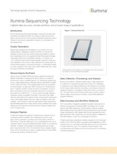
www.illumina.comeach channel of the flow cell. Figure 8: Determine First Base The first sequencing cycle begins by adding four labeled reversible After laser excitation, the emitted fluorescence from each cluster is captured terminators, primers, and DNA polymerase. Attached Attached Clusters Laser Figure 9: Image First Base and the first base is identified.

STM32™'s ADC modes and their applications
www.st.comADC sequencer converting 7 channels with different configured sampling ... channel sequence (with scan enabled and the sequencer of each ADC configured) or converts a single channel (scan disabled). The conversion can be started with an external trigger or by software. In this mode, the conversion results of ADC1 and ADC2 are stored in