AC Electrical Circuit Analysis - MVCC
Chapters on series, parallel and series-parallel RLC circuits commence. Following these, network theorems along with nodal and mesh analysis are discussed for the AC case. The text completes with chapters on AC power, resonance, and introductions to polyphase systems and magnetic circuits.
Download AC Electrical Circuit Analysis - MVCC

Information
Domain:
Source:
Link to this page:
Documents from same domain
Laboratory Manual for Semiconductor Devices
www2.mvcc.eduEmbedded Controllers Using C and Arduino, and Science of Sound. OER texts for DC and AC Electrical Circuit Analysis, Embedded Controllers, and Operational Amplifiers & Linear Integrated Circuits are also available. Finally, this work supersedes the earlier “Laboratory Manual for Linear Electronics”. A Note from the Author

DC Electrical Circuit Analysis - MVCC
www2.mvcc.eduPreface Welcome to DC Electrical Circuit Analysis, an open educational resource (OER).The goal of this text is to introduce the theory and practical application of analysis of DC electrical circuits. It is offered free of charge under a Creative Commons non-commercial, share-alike with attribution license.

2 Laboratory Manual for Linear Electronics
www2.mvcc.edu4 Laboratory Manual for Linear Electronics This Laboratory Manual for Linear Electronics, by James M. Fiore is copyrighted under the terms of a Creative Commons license: This work is freely redistributable for non-commercial use, share-alike with attribution
Laboratory Manual for Computer Programming with …
www2.mvcc.eduThis laboratory manual is intended for use in an introductory computer programming course for electrical engineering technology students. It begins with a basic explanation of schematic capture and simulation tools and proceeds to the Python programming language. Python (version 3.X) was chosen for several reasons.

Digital Electronics 1 (ET181) Laboratory Manual
www2.mvcc.eduMar 21, 2018 · • Knight electronics ML-2001 logic trainer • Digital multimeter (DMM) • Logic probe Discussion: The digital logic trainer used in this lab includes a number of features to support the design and fabrication of logic circuits in the lab. The main features include: • Fixed and variable positive and negative DC power supplies
Related documents
`Ohm’s Law III -- Resistors in Series and Parallel - University …
www.phys.utk.eduOhm’s Law III—Resistors in Series and Parallel connected in parallel can be found using the same general procedure and will result in the relationship N Tii=1 1 = RR ∑1. (21) In circuits with combinations of resistors in series and parallel, the total resistance can be
Electrical Circuits - University of Washington
sites.math.washington.eduSimple Series or Parallel Circuits For simple circuits, such as those used in math textbooks to introduce systems of equations, it is often sufficient to use series and parallel relationships to simplify circuits. With this done, Ohm’s Law (V=RI) can be used to find voltages or currents.

EE301 - PARALLEL CIRCUITS AND KIRCHHOFF’S CURRENT …
www.usna.eduHomes and ships are usually wired in parallel instead of in series. The reason: The parallel circuit will continue to operate even though one component may fail open. All components can operate at rated voltage independent of other loads when wired in parallel. Series - Parallel Circuits Circuits may contain a combination of series and parallel ...
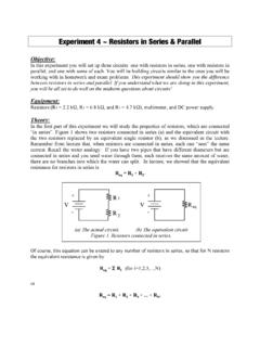
Experiment 4 ~ Resistors in Series & Parallel
www.umsl.eduparallel, and one with some of each. You will be building circuits similar to the ones you will be working with in homework and exam problems. This experiment should show you the difference between resistors in series and parallel. If you understand what we are doing in this experiment, you will be all set to do well on the midterm questions ...

Lab Report 2 RLC Circuits - obaidtech.com
www.obaidtech.comThen we had to connect them in parallel and nd the values; the connections were made as shown in the gure below: Figure 2: After nding the related values we had to construct the phasor diagrams. 4.3 Exercise 3 - Resonance of series RLC circuits Finally we were required to observe the e ects of resonance frequency in a series RLC circuit.

2600B System SourceMeter SMU Instruments
download.tek.comSeries 2600B’s to be inter-connected and function as a single, tightly-synchronized, multi-channel system. The 2600B’s TSP-Link Technology works together with its TSP technology to enable high-speed, SMU-per-pin parallel testing. Unlike other high-speed solutions such as large ATE systems, the 2600B achieves parallel test
RC and RL Circuits - Cleveland Institute of Electronics
cie-wc.eduMay 03, 2011 · RC and RL Circuits Rules to remember •ELI the ICE man: Voltage (E) leads Current (I) in an Inductive (L) circuit , whereas Current (I) leads Voltage (E) in a Capacitive (C) circuit –This is only true for SERIES circuits. When it goes into a parallel configuration, the opposite occurs •Current leads Voltage in a Parallel Inductive circuit