Search results with tag "Series circuits"

DC Electrical Circuit Analysis - MVCC
www2.mvcc.eduSubsequent chapters introduce resistance, series circuits, parallel circuits and series-parallel circuits. The text continues with chapters covering network theorems, more advanced techniques such as nodal and mesh analysis, and finally finishes with introductions to capacitors, inductors and magnetic circuits. The companion AC
E40M RC Circuits and Impedance - Stanford University
web.stanford.eduEKG (Lab 4) • Concepts –Amplifiers –Impedance –Noise –Safety –Filters • Components ... Impedance of Other RC Circuits Series: Z eq =Z 1 +Z 2 =R 1 +R 2 R 1 R 2 R 1 R 2 1C 2 C 2 C 1 ... –Calculate series and parallel effective impedances. Title: 13. RC Circuits, Impedance

RLC Resonant Circuits - University of Cambridge
mlg.eng.cam.ac.ukFor the simple parallel RLC circuit shown in gure 5 this is just equal to the rms supply voltage but for the series RLC circuit it is given by a potential divider rule. Therefore, for series circuits it is in general simpler to calculate the max energy stored by considering the inductor and in parallel circuits by considering the capacitor.
RC and RL Circuits - Cleveland Institute of Electronics
cie-wc.eduMay 03, 2011 · RC and RL Circuits Rules to remember •ELI the ICE man: Voltage (E) leads Current (I) in an Inductive (L) circuit , whereas Current (I) leads Voltage (E) in a Capacitive (C) circuit –This is only true for SERIES circuits. When it goes into a parallel configuration, the opposite occurs •Current leads Voltage in a Parallel Inductive circuit

Impedance Matching - QSL.net
www.qsl.net• In parallel resonant circuits, high-value loading resistors lead to high-Q, while in series circuits the opposite is true. • A broader band match usually can be obtained when the tuning is performed close to the load. Accepting an approximate match at the center frequency may result in a better average match over the operating band.

Series versus Parallel Lab - The Physics Classroom
www.physicsclassroom.comSeries versus Parallel Lab ... To compare the characteristics of series circuits to the characteristics of parallel circuits. A complete ...

Molded Case Circuit Breakers - Siemens
assets.new.siemens.comSeries connected short circuit ratings The term “Series Connected Short Circuit Rating” refers to the application of series circuit breakers in a combination that allows downstream breakers to have lower individual interrupting ratings than the available fault current. This is permitted as long as the series combination has been tested and ...

Experiment 10 ~ RLC Series circuit
www.umsl.eduExperiment 10 ~ RLC Series circuit Resonance in an RLC Series Circuit Objective: To experimentally determine the resonance frequency in a series RLC circuit and compare this to
Basic Electrical Engineering for HVAC Engineers
www.cedengineering.comHere are the basic rules of a series circuit. • Current: In a series circuit the current (I) in amperes is the same everywhere in the circuit. IT= I1 = I2 = I3 • Voltage: The total voltage of the circuit will be the sum of the voltages across each of the resistors in …

EFD and EFDC Series Circuit Explosionproof 3C Breakers and ...
www.cooperindustries.com507 3C www.crouse-hinds.com US: 1-866-764-5454 CAN: 1-800-265-0502 Copyright© 2013 Eaton’s Crouse-Hinds Business EFD and EFDC Series Circuit Breakers and ...

Basic circuit analysis - City U
cktse.eie.polyu.edu.hkProf. C.K. Tse: Basic Circuit Analysis 15 Voltage/current division For the series circuit, we can find the voltage across each resistor by the formula: Note the choice of R and G in the formulae! For the parallel circuit, we can find the voltage across each resistor by the formula:

RLC Circuit - Iowa State University
apps-dso.sws.iastate.eduRelated Problems 1) You have a 200 ohm resistor, a 0.400-H inductor. Suppose you take the resistor and inductor and make a series circuit with a voltage source that has voltage amplitude 30.0 V and an angular frequency of 250 rad/s. For this R-L circuit graph V, VR, and VL versus t for t = 0 to t = 50.0 ms.
A Textbook of Electrical Technology Vol. 2 - Theraja
www.kurratul.weebly.comRotor Output—EQuivalent Circuit Of the Rotor—EQuivalent Circuit Of an Induction Motor—Power Balance EQuation— Maximum Power Output—Corresponding Slip. 35. Computation And Circle Diagrams General—Circle Diagram for a Series Circuit—Circle Diagram of the Approximate Euuivalent Circle—Dctcrmination of GO and Rotor Test—Construction
Circuit A Circuit B - Livingston Public Schools
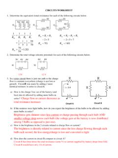
www.livingston.orgg) Fill out the table for the circuit diagramed at the right. 0.3 h) Is there a relationship between resistance and voltage drop in a series circuit? If so, state it. Ohm’s Law: V = IR c) If the resistors were light bulbs, explain in terms of charge flow (current) and energy per charge (voltage) which bulb would be brightest / dimmest.

for automotive, home, marine and RVs. - Cooper Industries
www.cooperindustries.comAutomotive and hardware/home center product catalog BUSSMANN SERIES Circuit protection technology for automotive, home, marine and RVs.
Similar queries
Series circuits, Parallel circuits, Series, Circuits, Impedance, Circuits Series, Series and parallel, Parallel, Series versus Parallel Lab, Physics, Circuit, Siemens, SERIES Circuit, Experiment 10 ~ RLC Series circuit, Breakers, Series Circuit Breakers, Problems, Electrical, For automotive, home, marine and RVs, Cooper Industries