
Analog Discovery ™ Technical Reference Manual
• Spectrum Analyzer - power spectrum and spectral measurements (noise floor, SFDR, SNR, THD, etc.) • Digital Bus Analyzers (SPI, I2C, UART, Parallel) Figure 1. The Analog Discovery. Features include:
Download Analog Discovery ™ Technical Reference Manual

Information
Domain:
Source:
Link to this page:
Documents from same domain
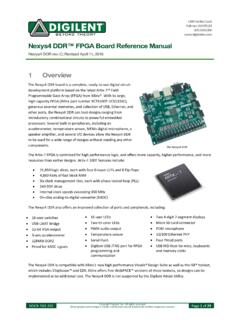
Nexys4 DDR™ FPGA Board Reference Manual - Digilentinc
digilent.comType A USB Host Connector (J5) Serial Prog. Port 2 6-pin JTAG Header (J10) Prog Micro SD Connector (J1) Media Select (JP2) User I/O M2 Mode (JP 1) Programming Mode JP2 JP1 NA SPI Flash NA JTAG USB MicroSD Figure 3. Nexys4 DDR configuration options. Figure 3 shows the different options available for configuring the FPGA. An on-board “mode ...
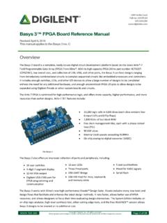
Basys 3™ FPGA Board Reference Manual - Digilent Reference
digilent.comPIC24 Type A USB Host Connector (J2) Serial Prog. Port 2 6-pin JTAG Header (J5) Prog M2 Mode (JP1) Programming Mode JP1 SPI Flash JTAG USB Figure 3. Basys 3 configuration options. The FPGA configuration data is stored in files called bitstreams that have the .bit file extension. The Vivado

ZedBoard HW Users Guide - Digilent Reference
digilent.comAug 01, 2012 · DDR3 on the PS was routed with 40 ohm trace impedance for single-ended signals, and DCI resistors (VRP/VRN) as well as differential clocks set to 80 ohms. Each DDR3 chip needs its own 240-ohm pull-down on ZQ. DDR-VDDQ is set to 1.5V to support the DDR3 devices selected. DDR-VTT is the termination voltage which is ½ DDR-VDDQ.

Nexys A7 FPGA Board Reference Manual - Digilentinc
digilent.comThe major improvement from the Nexys 4 to the Nexys 4 DDR is the replacement of the 16 MiB Cellular RAM with a 128 MiB DDR2 SDRAM memory. Furthermore, to accommodate the new memory, the pin-out of the FPGA banks changed as well. The audio output (AUD_PWM) needs to be driven open-drain as opposed to push-pull on the Nexys 4. 1 Functional Description

Zybo Z7 Board Reference Manual - Digilentinc
digilent.com• High-bandwidth peripheral controllers: 1G Ethernet, USB 2.0, SDIO • Low-bandwidth peripheral controllers: SPI, UART, CAN, I2C • Programmable from JTAG, Quad-SPI flash, and microSD card • Programmable logic equivalent to Artix-7 FPGA

Arty™ FPGA Board Reference Manual - Digilent Reference
digilent.comport (J10) or it can be derived from a 7 to 15 Volt D power supply that [s connected to Power Jack (J12) or Pin 8 of Header J7. Header J13, located between the power jack and the Ethernet connector, is used to determine which source is used. A power-good LED (LD11), driven by the power good _ (PWRGD) output of the ADP5052 regulator, indicates that

ZYBO - Digilentinc
digilent.comMay 31, 2017 · zybo z7 board digilen t inc. a vailable on z20 v er sion only pibtn401 pibtn402 pibtn403 cobtn4 pibtn404 pibtn501 pibtn502 pibtn503 cobtn5 pibtn504 pid101 pid102 pid103 pid104 pid105 cod1 pid201 pid202 pid203 pid204 pid205 cod2 pid301 pid302 pid303 pid304 pid305 cod3 pid401 pid402 pid403 pid404 pid405 cod4 ...

Analog Discovery 2™ Reference Manual
digilent.comStereo audio amplifier to drive external headphones or speakers with replicated AWG signals 16-channel pattern generator (3.3V CMOS, 100Msample/sec)i ii 16-channel virtual digital I/O including buttons, switches, and LEDs – perfect for logic training applicationsiii iv 16-channel digital logic analyzer (3.3V CMOS,
Digilent Pmod Interface Specification
digilent.comhost controller boards. There are six-pin and twelve-pin versions of the interface defined. The six-pin ... Microcontroller system boards are generally provided with dedicated I 2C connectors and provide pull-up resistors that are jumper selectable to be in or out of circuit. FPGA based system boards generally

Introduction to Digital Design Using Digilent FPGA Boards
digilent.comExample 9 – 7-Segment Decoder 48 Example 10 – 7-Segment Displays: x7seg and x7segb 54 Example 11 – 2's Complement 4-Bit Saturator 64 Example 12 – Full Adder 70 ... digital circuit and implement it by connecting the internal gates in a particular way. This
Related documents
Solar Cell Voltage-Current Characterization
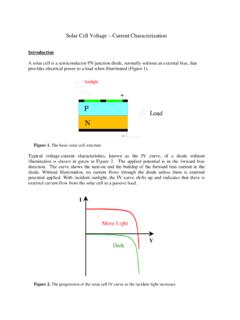
www.californiascientific.comShort circuit current, Isc, flows with zero external resistance (V= 0) and is the maximum current delivered by the solar cell at any illumination level. Similarly, the open circuit voltage, Voc, is the potential that develops across the terminals of the solar cell when the external load resistance is very large (Figure 3).

An Introduction to Mass Spectrometry
science.widener.eduData System Mass Detector Analyzer Vacuum System Source Inlet Region *More precisely mass spectrometry determines the mass of a molecule. **The mass to charge ratio ( m/z) is used to describe ions observed in mass spectrometry.By convention, m is the numerical value for the mass of the ion and z is the numerical value for the charge of the ion.

THEORY OF XRF
www.chem.purdue.eduenergy surplus can be emitted as an X-ray photon. In a spectrum, this is seen as a line. The energy of the emitted X-rays depends on the difference in energy between the shell with the initial hole and the energy of the electron that fills the hole (in the example, the difference between the energy of the K and the L shell). Each atom

The Fundamentals of FFT-Based Signal Analysis and …
www.sjsu.eduspectrum and network analyzers. By using plug-in DAQ devices, you can build a lower cost measurement system and avoid the communication overhead of working with a stand-alone instrument. Plus, you have the flexibility of configuring your measurement processing to …

Tutorial on Measurement of Power Spectra
123.physics.ucdavis.eduunits and displays as shown on traditional benchtop spectrum and network analyzers. By using plug-in DAQ devices, you can build a lower cost measurement system and avoid the communication overhead of working with a stand-alone instrument. Plus, you have the flexibility of configuring your measurement processing to meet your needs.
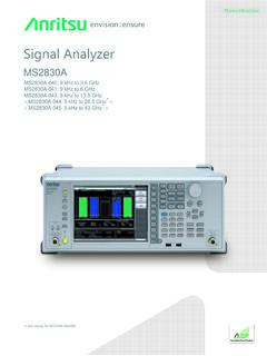
Signal Analyzer MS2830A Brochure
dl.cdn-anritsu.comother spectrum analyzers ignores the important frequency characteristics, linearity, and attenuator switching errors. The MS2830A calibration technology supports excellent level accuracy over the wide frequency range from 300 kHz to 4 GHz even under measurement conditions including the above three errors. Dynamic Range*1: 168 dB TOI*2: ≥+15 dBm

APPLICATION NOTE AN014 Understanding FFTWindows
www.egr.msu.educalculation of the spectrum. This means that more aver-ages must be taken to get a good statistical representa-tion of the spectrum, increasing the time to complete the measurement. Overlap processing is a feature that is available in most signal analyzers that can recover the lost data and reduce the measurement time. This pro-

N9020B MXA X-Series Signal Analyzer, Multi-touch
www.keysight.comNov 05, 2021 · DATA SHEET N9020B MXA X-Series Signal Analyzer, Multi-touch 10 Hz to 3.6, 8.4, 13.6, 26.5, 32, 44, or 50 GHz