Transcription of Nexys4 DDR™ FPGA Board Reference Manual - Digilentinc
1 1300 Henley Court Pullman, WA 99163 Nexys4 DDR FPGA Board Reference Manual Nexys4 DDR rev. C; Revised April 11, 2016 DOC#: 502-292 Copyright Digilent, Inc. All rights reserved. Other product and company names mentioned may be trademarks of their respective owners. Page 1 of 29 1 Overview The Nexys4 DDR Board is a complete, ready-to-use digital circuit development platform based on the latest Artix-7 Field Programmable Gate Array (FPGA) from Xilinx . With its large, high-capacity FPGA (Xilinx part number XC7A100T-1 CSG324C), generous external memories, and collection of USB, Ethernet, and other ports, the Nexys4 DDR can host designs ranging from introductory combinational circuits to powerful embedded processors.
2 Several built-in peripherals, including an accelerometer, temperature sensor, MEMs digital microphone, a speaker amplifier, and several I/O devices allow the Nexys4 DDR to be used for a wide range of designs without needing any other components. The Artix-7 FPGA is optimized for high performance logic, and offers more capacity, higher performance, and more resources than earlier designs. Artix-7 100T features include: 15,850 logic slices, each with four 6-input LUTs and 8 flip-flops 4,860 Kbits of fast block RAM Six clock management tiles, each with phase-locked loop (PLL) 240 DSP slices Internal clock speeds exceeding 450 MHz On-chip analog-to-digital converter (XADC) The Nexys4 DDR also offers an improved collection of ports and peripherals, including.
3 16 user switches 16 user LEDs Two 4-digit 7-segment displays USB-UART Bridge Two tri-color LEDs Micro SD card connector 12-bit VGA output PWM audio output PDM microphone 3-axis accelerometer Temperature sensor 10/100 Ethernet PHY 128 MiB DDR2 Serial Flash Four Pmod ports Pmod for XADC signals Digilent USB-JTAG port for FPGA programming and communication USB HID Host for mice, keyboards and memory sticks The Nexys4 DDR is compatible with Xilinx s new high-performance Vivado Design Suite as well as the ISE toolset, which includes ChipScope and EDK.
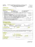
4 Xilinx offers free WebPACK versions of these toolsets, so designs can be implemented at no additional cost. The Nexys4 DDR is not supported by the Digilent Adept Utility. The Nexys4 DDR Nexys4 DDR FPGA Board Reference Manual Copyright Digilent, Inc. All rights reserved. Other product and company names mentioned may be trademarks of their respective owners. Page 2 of 29 Callout Component Description Callout Component Description 1 Power select jumper and battery header 13 FPGA configuration reset button 2 Shared UART/ JTAG USB port 14 CPU reset button (for soft cores) 3 External configuration jumper (SD / USB) 15 Analog signal Pmod port (XADC) 4 Pmod port(s) 16 Programming mode jumper 5 Microphone 17 Audio connector 6 Power supply test point(s) 18 VGA connector 7 LEDs (16)
5 19 FPGA programming done LED 8 Slide switches 20 Ethernet connector 9 Eight digit 7-seg display 21 USB host connector 10 JTAG port for (optional) external cable 22 PIC24 programming port (factory use) 11 Five pushbuttons 23 Power switch 12 Temperature sensor 24 Power jack A growing collection of Board support IP, Reference designs, and add-on boards are available on the Digilent website. See the Nexys4 DDR page at for more information. Figure 1. Nexys4 DDR Board features. Nexys4 DDR FPGA Board Reference Manual Copyright Digilent, Inc.
6 All rights reserved. Other product and company names mentioned may be trademarks of their respective owners. Page 3 of 29 Migrating from Nexys4 The Nexys4 DDR is an incremental update to the Nexys4 Board . The major improvement is the replacement of the 16 MiB CellularRAM with a 128 MiB DDR2 SDRAM memory. Digilent will provide a VHDL Reference module that wraps the complexity of a DDR2 controller and is backwards compatible with the asynchronous SRAM interface of the CellularRAM, with certain limitations. See the Nexys4 DDR page at for updates.
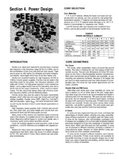
7 Furthermore, to accommodate the new memory, the pin-out of the FPGA banks has changed as well. The constraints file of existing projects will need to be updated. The audio output (AUD_PWM) needs to be driven open-drain as opposed to push-pull on the Nexys4 . 2 Power Supplies The Nexys4 DDR Board can receive power from the Digilent USB-JTAG port (J6) or from an external power supply. Jumper JP3 (near the power jack) determines which source is used. All Nexys4 DDR power supplies can be turned on and off by a single logic-level power switch (SW16).
8 A power-good LED (LD22), driven by the power good output of the ADP2118 supply, indicates that the supplies are turned on and operating normally. An overview of the Nexys4 DDR power circuit is shown in Figure 2. Power Jack (J13) : ADP2118 PowerSwitch (SW16)Power OnLED (LD22)Micro-USB Port (J6)VU5V0J12IC23: ADP2138EN800 mAVINIC22: Source Figure 2. Nexys4 DDR power circuit. The USB port can deliver enough power for the vast majority of designs. Our out-of-box demo draws ~400mA of current from the 5V input rail.
9 A few demanding applications, including any that drive multiple peripheral boards, might require more power than the USB port can provide. Also, some applications may need to run without being connected to a PC s USB port. In these instances, an external power supply or battery pack can be used. An external power supply can be used by plugging into to the power jack (JP3) and setting jumper J13 to wall . The supply must use a coax, center-positive internal-diameter plug, and deliver to and at Nexys4 DDR FPGA Board Reference Manual Copyright Digilent, Inc.
10 All rights reserved. Other product and company names mentioned may be trademarks of their respective owners. Page 4 of 29 least 1A of current ( , at least 5W of power). Many suitable supplies can be purchased from Digilent, through Digi-Key, or other catalog vendors. An external battery pack can be used by connecting the battery s positive terminal to the center pin of JP3 and the negative terminal to the pin labeled J12, directly below JP3. Since the main regulator on the Nexys4 DDR cannot accommodate input voltages over , an external battery pack must be limited to The minimum voltage of the battery pack depends on the application: if the USB Host function (J5) is used, at least needs to be provided.