Chapter 2 Aircraft Structure
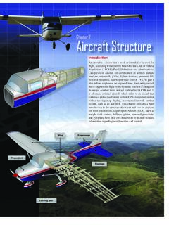
2-3 Figure 2-4. Airplane components. Figure 2-5. Truss-type fuselage structure. Figure 2-3. Center of gravity (CG). Major Components Although airplanes are designed for a variety of purposes, most of them have the same major components. [Figure 2-4] The overall characteristics are largely determined by the original design objectives.
Download Chapter 2 Aircraft Structure

Information
Domain:
Source:
Link to this page:
Documents from same domain
S. L. ten Cate 08-2015 - University of Florida
mae.ufl.eduThe most common types of pipe thread are: • NPT - American Taper Pipe Thread = National Pipe Taper • NPTF - American Taper Pipe Thread for Dryseal joint without sealant compound = National Pipe Taper Fuel NPT and NPTF appear to be identical. Both have the same pitch diameter at the top of the hole of the internal thread or end of the pipe ...

Fundamental Principles of Mechanical Design
mae.ufl.eduMechanical Design Fundamentals K. Craig 20 Laws of Nature • To develop a physical model of an existing system or of a system concept, we use engineering judgment and make simplifying assumptions. • To develop a mathematical model, a model that can predict system dynamic behavior, we apply the Laws of Nature to the physical model.
Useful Motor/Torque Equations for EML2322L
mae.ufl.eduCalculate the Torque required to lift the Force with the lever arm . T = F x d = 49.05 N x 0.5 m = 24.525 N-m . We cannot perform the lift with this set-up, because the stall torque is smaller than . the torque required for the lift. We must either shorten the length of the lever arm,

Drive Wheel Motor Torque Calculations
mae.ufl.eduDrive Wheel Motor Torque Calculations . Step Four: Determine Total Tractive Effort . The Total Tractive Effort (TTE) is the sum of the forces calculated in steps 1, 2, and 3. (On higher speed vehicles friction in drive components may warrant the addition of 10%-15% to the total tractive effort to ensure acceptable vehicle performance.)
Drilling Speeds and Feeds - University of Florida
mae.ufl.eduEquation 2 will provide a guideline as to the maximum speed when drilling standard materials. The optimum speed for a particular setup is affected by many factors, including the following: 1. composition, hardness, and thermal conductivity (k) of material 2. depth of hole 3. efficiency of cutting fluid 4. stiffness and condition of drilling ...

CHAP 4 FINITE ELEMENT ANALYSIS OF BEAMS AND FRAMES
mae.ufl.edu1 CHAP 4 FINITE ELEMENT ANALYSIS OF BEAMS AND FRAMES 2 INTRODUCTION • We learned Direct Stiffness Method in Chapter 2 – Limited to simple elements such as 1D bars • we will learn Energy Methodto build beam finite element – Structure is in equilibrium when the potential energy is minimum

Engineering Change Notice - University of Florida
mae.ufl.eduEngineering Change Notice Definition . An . Engineering Change Notice (ECN) is a document authorizing and recording design changes throughout the prototyping and life-cycle phases of a product. ECN documentation contains the ... The drawings must clearly show the detail(s) affected by the change. ...

Tap & Drill Chart
mae.ufl.eduDrill Size Dec. Eq. Drill Size Dec. Eq. Drill Size Dec. Eq. Drill Size Dec. Eq. 0 0.060 80 0.045 3/64 0.047 55 0.052 52 0.064 50 0.070 64 0.054 53 0.060 1/16 0.063

Engineering Design Representation
mae.ufl.eduExternal threads refers to threads cut or rolled into the external cylindrical surface of a fastener or stud. The size most commonly associated with screw threads is the nominal diameter. Nominal diameter is a more of a label than a size. For example, a bolt and nut

EML 2322L – MAE Design and Manufacturing Laboratory ...
mae.ufl.eduEML 2322L – MAE Design and Manufacturing Laboratory . Dimensioning Rules . 1. Each dimension should be given clearly so it can be interpreted in only one way. 2. Dimensions should not be duplicated or the same information given in …
Related documents

Topic 14 - Foundation Design - Memphis
www.ce.memphis.eduInstructional Materials Complementing FEMA 451, Design Examples Foundation Design 14-38 Tie Between Pile Caps (2) #6 top bars (3) #6 bottom bars #4 ties at 7" o.c. 2" clear at sides 3" clear at top and bottom •Designed for axial force (+/-) •Pile cap axial load times S DS/10 •Often times use grade beams or thickened slabs one grade

DESIGN RECOMMENDATION FOR STORAGE TANKS AND …
www.aij.or.jp3.2 Dead Loads ----- 9 3.3 Live Loads ----- 9 ... Qd design yield shear force at the base of the structure (N) Qdi design shear force imposed just below the i-th mass in case that the structure is

CALCULATING WIND LOADS ON LOW-RISE STRUCTURES PER …
www.awc.orgC1.1.2 Design Loads Unless stated otherwise, all calculations are based on standard linear elastic analysis and Allowable Stress Design (ASD) load combinations using loads from ASCE 7-10 Minimum Design Loads for Buildings and Other Structures. Dead Loads Unless stated otherwise, tabulated values assume the following dead loads: Roof pf10 psf