
Chapter 6 Synchronous Sequential Circuits
In a combinational circuit, the values of the outputs are determined solely by the present values of its inputs. In a sequential circuit, the values of the outputs depend on the past behavior of the circuit, as well as the present values of its inputs. A sequential circuit has states, which in conjunction with the present values of inputs
Download Chapter 6 Synchronous Sequential Circuits

Information
Domain:
Source:
Link to this page:
Documents from same domain

3. The Finite-Difference Time- Domain Method (FDTD)
my.ece.utah.edu3. The Finite-Difference Time-Domain Method (FDTD) The Finite-Difference Time-Domain method (FDTD) is today’s one of the most popular technique for the solution of electromagnetic problems. It has been successfully applied to an extremely wide variety of problems, such as scattering from metal objects and

MatlabTutorial : Root Locus
my.ece.utah.edu2.0 Root Locus Design Consider all positive values of k. In the limit as k -> 0, the poles of the closed-loop system are a(s) = 0 or the poles of H(s). In the limit as k -> infinity, the poles of the closed-loop system are b(s) = 0 or the zeros of H(s). No matter what we pick k to be, the closed-loop system must always have n poles, where n is the

ECE 5325/6325: Wireless Communication Systems Lecture ...
my.ece.utah.eduControl was manual, and the control channel was open for anyone to hear. In fact, users were required to be listening to the control channel. When the switching operator wanted to connect to any mobile user, they would announce the call on the control channel. If the user responded, they would tell the user which voice channel to turn to.

Solving the Generalized Poisson Equation Using the Finite ...
my.ece.utah.eduFinite-Di erence Method (FDM) James R. Nagel, nageljr@ieee.org Department of Electrical and Computer Engineering University of Utah, Salt Lake City, Utah February 15, 2012 1 Introduction The Poisson equation is a very powerful tool for modeling the behavior of …

Introduction to Bode Plot - University of Utah
my.ece.utah.edus TF sss + = ++ Simplify transfer function form: 200*20 (1)100(1) 200(20) 402020 (21)(40) (1)(1)(1)(1) 0.5400.540 ss s TF sss ssss ss ++ + === ++ ++++ Recognize: K = 100 à 20 log10(100) = 40 1 pole at the origin 1 zero at z 1 = 20 2 poles: …

Homework #3 Solution - University of Utah
my.ece.utah.eduHomework #3 Solution mirror, such as that shown at the right, all µA/V 2, L=1µm, and V A=10V. Widths reference current IREF is 20µA. What 2 and Q 3? -source operation is and ro of Q 2 and Q 3? What is the output 1 . Fall 2010 2. Find the output …

MET 382 PLC Fundamentals - Ladder fundamentals - Spr …
my.ece.utah.eduMET 382 1/14/2008 Ladder Logic Fundamentals 2 PLC Programming Languages In the United States, ladder logic is the most pppopular method used to program a PLC This course will focus primarily on ladder logic programming Other programming methods include: Function block diagrams (FBDs) 3 Structured text (ST)
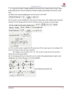
Homework #1 - University of Utah
my.ece.utah.eduHomework #1 Fall 2010 3 4. For the circuit below: (a) Find the resistances looking into node 1, R1; node 2, R2; node 3, R3; and node 4, R4. (b) Find the currents I1, I 2, I 3, and I4 in terms of the input current I. (c) Find the voltage at nodes 1,2,3, and 4, that is V1, V2, V3, and V4 in terms of IR.

ECE 5520: Digital Communications Lecture Notes Fall 2009
my.ece.utah.eduA digital communication system conveys discrete-time, discrete-valued information across a physical channel. Information sources might include audio, video, text, or data. They might be continuous-time (analog) signals (audio, images) and even 1-D or 2-D. Or, they may already be digital (discrete-time, discrete-valued). Our
Related documents

Understanding LED Drivers - 1000Bulbs.com
www.1000bulbs.comDimmable external drivers often require an external dimmer, or other dimming control devices specified on the product datasheet (namely TRIAC, Trailing Edge, or 1-10v dimmers) to work. Since technologies are improving rapidly, it’s best to test specific LED/dimmable driver combinations for
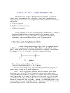
HYDRAULIC CIRCUIT DESIGN AND ANALYSIS
www.nitc.ac.inHYDRAULIC CIRCUIT DESIGN AND ANALYSIS A Hydraulic circuit is a group of components such as pumps, actuators, and control valves so arranged that they will perform a useful task. When analyzing or designing a hydraulic circuit, the following three important considerations must be taken into account: 1. Safety of operation 2.

11. The Series RLC Resonance Circuit
www.hunter.cuny.eduWhat we actually have control over is the signal generator voltage frequency f measured in Hz and w=2pf is the relationship between the two frequencies. Combining equations (1) through (3) above together with the time varying signal generator we get Kirchoff's loop equation for a series RLC circuit. L (4) d dt i@tD+ Q@tD C +i@tD R = V0 Sin@wtD

Audio Amplifier Circuit - UC Santa Barbara
web.ece.ucsb.edu1.2 Speaker Equivalent Circuit 9 1.3 Assemble Amplifier on Breadboard 9 1.4 Summing network 11 1.5 Optional -- Tone-Control Circuit 12 1.6 Hardwire the Amplifier 13 1.7 Possible Improvements 14 Pre-lab Preparation Before Coming to the Lab Read through the lab experiment to familiarize yourself with the components and

NEMA and IEC schematic diagram comparisons - MZ081001EN
www.eaton.comControl circuit Common Schematic Diagrams: Across the Line Non-Reversing Starters with Hand–Off–Auto Selector Switch Power circuit—starter Control circuit—starter. 7 Cross-Reference MZ081001EN Effective November 2013

Chapter 7 Gate Drive circuit Design - Fuji Electric
www.fujielectric.comincrease switching losses. lower Rg adding CGE at the same time can control switching However, speed. In other words, both adding the CGE and decreasing the RG can avoid the unexpected turn -on ... Fig.7-4 shows the circuit schematic as well as the voltage and current waveforms. In principle,

LED Drive Control Special Circuit TM1637 1 K2 20 SEG1/KS1 K1
www.mcielectronics.clLED Drive Control Special Circuit TM1637 1 ©Titan Micro Electronics www.titanmec.com V2.4 Features description GND TM1637 is a kind of LED (light-emitting diode display) drive control special circuit with keyboard scan interface and it's internally integrated with MCU digital interface, data latch, LED high pressure ...

SHORT CIRCUIT CURRENT RATINGS - Mouser Electronics
www.mouser.comCurrent Ratings for Industrial Control Panels Introduction A short-circuit current rating (SCCR)1 is the maximum current a device or system can safely withstand for a specified time (such as 0.05 seconds), or until a specified fuse or circuit breaker opens and clears the circuit. SCCR is usually expressed in kiloamperes (kA).