Search results with tag "Toledo bp"

Refinery General Rules Booklet - Toledo BP
toledobp.comGeneral Rules booklet 3 BP’s COMMITMENT TO HEALTH, SAFETY AND ENVIRONMENTAL PERFORMANCE Everybody who works for BP, anywhere, is responsible for

Sketching Bode Plots by Hand - eng.auburn.edu
www.eng.auburn.eduSketching Bode Plots by Hand MECH 3140. Lecture # Recall what a bode plot is • It is the particular solution to a LTI differential equation for a sinusoidal input • It shows how the output of a system will responds to different input frequencies (including constant inputs, i.e. ω=0)

EXAMPLES ON BODE PLOTS OF FIRST AND SECOND ORDER …
wonjongkim.tamu.eduHANDOUT E.17 - EXAMPLES ON BODE PLOTS OF FIRST AND SECOND ORDER SYSTEMS Example 1 Obtain the Bode plot of the system given by the transfer function 2 1 1 ( ) + = s G s. We convert the transfer function in the following format by substituting s = jω 2 1 1 ( ) + = ω ω j G j. (1) We call 2 1 ω = , the break point. So for 2 1 ω << , i.e., for ...

Introduction to Bode Plot - University of Utah
my.ece.utah.eduThe plot of the log magnitude vs. input frequency is only half of the story. We also need to be able to plot the phase angle vs. input frequency on a log scale as well to complete the full Bode diagram.. For our original transfer function, ( 1) ( 1) ( ) 1 1 1 1 + + = p jwp jw z Kz jw H jw the cumulative phase angle associated with this function ...

Frequency Analysis & Bode Plots - Mercer University
faculty.mercer.eduBode Plots for Systems with Complex Poles The asymptotic approaches described for real poles can be extended to systems with complex conjugate poles (and zeros). (Normalized) -1800 G(jo) = (jo)2 + 240.0) + IG(j lim O 1+2 ZG(j • 0) lim ZG(j. 0) =

EEE 151 (WFR and WFU) Analog and Digital Control COURSE …
202.92.132.69Bode Plots lectures 17, 18 (19, 24 Nov 2021) Define precisely what frequency response is. Draw Bode plots of first order and second order systems. Lab 02 report 19 Nov 2021 10 Bode Plots and Transfer Functions Compensation Using Bode Plots lectures 19, 20 (26 Nov 2021, 01 Dec 2021) Draw asymptotic Bode plots given a transfer function.

Frequency Response and Bode Plots
web.njit.eduof frequency-selective circuits. We will first consider how to generate Bode plots for simple poles, and then discuss how to handle the general second-order response. Before doing this, however, it may be helpful to review some properties of transfer functions, the decibel scale, and properties of the log function. Poles, Zeroes, and Stability

Tuning for PID Controllers - Mercer University
faculty.mercer.edustudied (Root Locus, Bode Plots) •System models may be determined using system identification techniques, such measuring output for an impulse or step input. •Traditional control design methods are less appropriate if the system is unknown; •Most PID controllers are tuned on-site due to machine and process variations. The theoretical
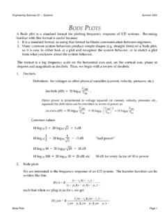
Bode plots
www.dartmouth.eduA Bode plot is a standard format for plotting frequency response of LTI systems. Becoming familiar with this format is useful because: 1. It is a standard format, so using that format facilitates communication between engineers. 2. Many common system behaviors produce simple shapes (e.g. straight lines) on a Bode plot,