
Chapter 6 Synchronous Sequential Circuits
Verilog code for the Mealy machine of Figure 6.23. Please see “portrait orientation” PowerPoint file for Chapter 6. Figure 6.37. Simulation results for the Mealy machine. Figure 6.38. Potential problem with asynchronous inputs to a Mealy FSM. Figure 6.39. Block diagram for the serial adder. Sum = A + B
Download Chapter 6 Synchronous Sequential Circuits

Information
Domain:
Source:
Link to this page:
Documents from same domain

3. The Finite-Difference Time- Domain Method (FDTD)
my.ece.utah.edu3. The Finite-Difference Time-Domain Method (FDTD) The Finite-Difference Time-Domain method (FDTD) is today’s one of the most popular technique for the solution of electromagnetic problems. It has been successfully applied to an extremely wide variety of problems, such as scattering from metal objects and

MatlabTutorial : Root Locus
my.ece.utah.edu2.0 Root Locus Design Consider all positive values of k. In the limit as k -> 0, the poles of the closed-loop system are a(s) = 0 or the poles of H(s). In the limit as k -> infinity, the poles of the closed-loop system are b(s) = 0 or the zeros of H(s). No matter what we pick k to be, the closed-loop system must always have n poles, where n is the

ECE 5325/6325: Wireless Communication Systems Lecture ...
my.ece.utah.eduControl was manual, and the control channel was open for anyone to hear. In fact, users were required to be listening to the control channel. When the switching operator wanted to connect to any mobile user, they would announce the call on the control channel. If the user responded, they would tell the user which voice channel to turn to.

Solving the Generalized Poisson Equation Using the Finite ...
my.ece.utah.eduFinite-Di erence Method (FDM) James R. Nagel, nageljr@ieee.org Department of Electrical and Computer Engineering University of Utah, Salt Lake City, Utah February 15, 2012 1 Introduction The Poisson equation is a very powerful tool for modeling the behavior of …

Introduction to Bode Plot - University of Utah
my.ece.utah.edus TF sss + = ++ Simplify transfer function form: 200*20 (1)100(1) 200(20) 402020 (21)(40) (1)(1)(1)(1) 0.5400.540 ss s TF sss ssss ss ++ + === ++ ++++ Recognize: K = 100 à 20 log10(100) = 40 1 pole at the origin 1 zero at z 1 = 20 2 poles: …

Homework #3 Solution - University of Utah
my.ece.utah.eduHomework #3 Solution mirror, such as that shown at the right, all µA/V 2, L=1µm, and V A=10V. Widths reference current IREF is 20µA. What 2 and Q 3? -source operation is and ro of Q 2 and Q 3? What is the output 1 . Fall 2010 2. Find the output …

MET 382 PLC Fundamentals - Ladder fundamentals - Spr …
my.ece.utah.eduMET 382 1/14/2008 Ladder Logic Fundamentals 2 PLC Programming Languages In the United States, ladder logic is the most pppopular method used to program a PLC This course will focus primarily on ladder logic programming Other programming methods include: Function block diagrams (FBDs) 3 Structured text (ST)
Homework #1 - University of Utah
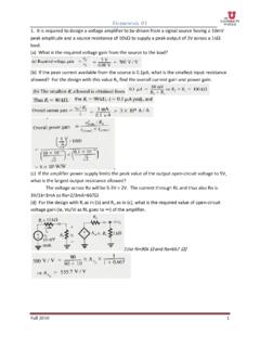
my.ece.utah.eduHomework #1 Fall 2010 3 4. For the circuit below: (a) Find the resistances looking into node 1, R1; node 2, R2; node 3, R3; and node 4, R4. (b) Find the currents I1, I 2, I 3, and I4 in terms of the input current I. (c) Find the voltage at nodes 1,2,3, and 4, that is V1, V2, V3, and V4 in terms of IR.

ECE 5520: Digital Communications Lecture Notes Fall 2009
my.ece.utah.eduA digital communication system conveys discrete-time, discrete-valued information across a physical channel. Information sources might include audio, video, text, or data. They might be continuous-time (analog) signals (audio, images) and even 1-D or 2-D. Or, they may already be digital (discrete-time, discrete-valued). Our
Related documents

Verilog HDL: A Guide to Digital Design and Synthesis
robo-tronix.weebly.comVerilog HDL allows different levels of abstraction to be mixed in the same model. Thus, a designer can define a hardware model in terms of switches, gates, RTL, or behavioral code. Also, a designer needs to learn only one language for stimulus and hierarchical design. Most popular logic synthesis tools support Verilog HDL. This makes it the
Verilog-2001 Quick Reference Guide - Sutherland HDL
sutherland-hdl.comVerilog HDL Quick Reference Guide 2 1.0 New Features In Verilog-2001 Verilog-2001, officially the “IEEE 1364-2001 Verilog Hardware Description Language”, adds several significant enhancements to the Verilog-1995 standard. • Attribute properties (page 4) • Generate blocks (page 21) • Configurations (page 43)
Vivado tutorial - Xilinx
www.xilinx.comNotice in the Verilog code that the first line defines the timescale directive for the simulator. Lines 2-5 are comment lines describing the module name and the purpose of the module. 1-2-3. Line 7 defines the beginning (marked with keyword module) and Line 19 defines the end of the module (marked with keyword endmodule). 1-2-4.

AXI4-Stream Infrastructure IP Suite v3 - Xilinx
www.xilinx.comAXI4-Stream Infrastructure IP Suite v3.0 4 PG085 November 17, 2021 www.xilinx.com Product Specification Introduction The AXI4-Stream Infrastructure IP Suite is a
ECE 128 Synopsys Tutorial: Using the Design Compiler ...
s2.smu.edu5) Load all your verilog code (and its dependent files) by going to: File->Analyze Click on the “add” button and click on the “src” sub-directory Add “fulladder.v” and “halfadder.v” Note : The analyze command will do syntax checking and create intermediate .syn files which will be stored in the directory work, the defined design library.
Verilog 1 - Fundamentals
cseweb.ucsd.eduVerilog, VHDL, SystemVerilog C, C++, SystemC Behavioral RTL Verilog, VHDL, SystemVerilog MATLAB Simulators and other tools are available at all levels but not compilers from the behavioral level to RTL