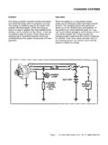
CHARGING SYSTEMS
1. Prepare the tester: • Rotate the Load Increase control to OFF, • Check each meter's mechanical zero. Adjust, if necessary. • Connect the tester Load Leads to the battery terminals; RED to positive, BLACK to negative. • Set Volt Selector to INT 18V. • Set Test Selector to #2 CHARGING. • Adjust ammeter to read ZERO using the electrical
Download CHARGING SYSTEMS

Information
Domain:
Source:
Link to this page:
Documents from same domain
GENERAL MOTORS - Autoshop 101
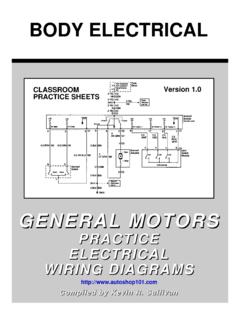
www.autoshop101.comBODY ELECTRICAL GENERAL MOTORS PRACTICE ELECTRICAL WIRING DIAGRAMS http://www.autoshop101.com Compiled by Kevin R. Sullivan CLASSROOM PRACTICE SHEETS
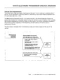
TOYOTA ELECTRONIC TRANSMISSION CHECKS & …
www.autoshop101.comDiagnosis During diagnosis, always verify the customer complaint. If the verification includes a test drive, be sure to check the level of ATF first.
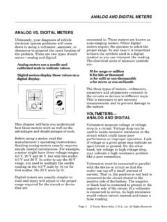
ANALOG AND DIGITAL METERS - Autoshop 101
www.autoshop101.comANALOG VS. DIGITAL METERS Ultimately, your diagnosis of vehicle electrical system problems will come down to using a voltmeter, ammeter, or ohmmeter to …
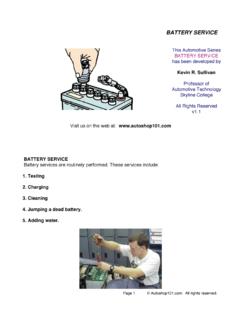
BATTERY SERVICE - Autoshop 101
www.autoshop101.comPage 1 © Autoshop101.com. All rights reserved. BATTERY SERVICE This Automotive Series BATTERY SERVICE has been developed by Kevin R. Sullivan
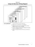
Section 2 Using the Electrical Wiring Diagram
www.autoshop101.comUsing the Electrical Wiring Diagram Body Electrical Diagnosis - Course L652 3 One of the keys to a quick and successful electrical diagnosis is correctly
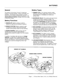
General Battery Types - Automotive Training and …
www.autoshop101.comGeneral The battery is the primary "source" of electrical energy on Toyota vehicles. It stores chemicals, not electricity. Two different types of lead in an acid
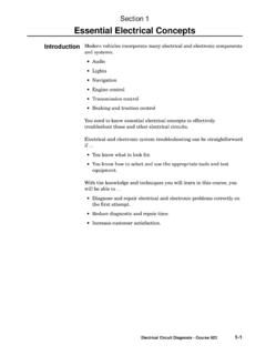
Section 1 Essential Electrical Concepts
www.autoshop101.comSection 1 1-2 TOYOTA Technical Training Different meters are used to measure voltage, current, and resistance: •Voltmeter - to measure voltage •Ammeter - to measure current
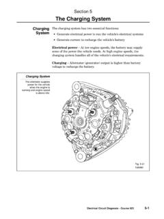
Section 5 The Charging System
www.autoshop101.comThe Charging System Electrical Circuit Diagnosis - Course 623 5-3 The alternator contains these main components: •Stator (attached to …
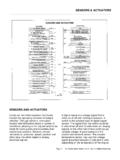
SENSORS AND ACTUATORS - Autoshop 101
www.autoshop101.comSENSORS AND ACTUATORS Computer controlled systems continually monitor the operating condition of today's vehicles. Through sensors, computers receive vital information about a number of
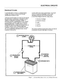
ELECTRICAL CIRCUITS Electrical Circuits - Autoshop …
www.autoshop101.comElectrical Circuits A complete path, or circuit, is needed before voltage can cause a current flow through resistances to perform work. …
Related documents
Section 5 The Charging System - Autoshop 101
www.autoshop101.comtester: 1. Set the tester’s Load control to OFF. 2. Connect the tester leads. •Red lead to positive terminal. •Black lead to negative terminal. •Clamp the ammeter clamp-on probe onto the battery’s ground cable. 3. Set the tester’s voltage range to the appropriate setting. 4. Zero both meters on the tester, if needed. 5.
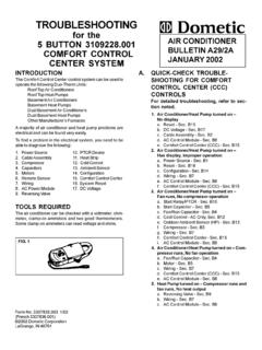
for the 5 BUTTON 3109228.001 AIR CONDITIONER COMFORT ...
bryantrv.comTION as 1 15 volt s may be present. If no voltage is present, the problem is in the coach wiring or breaker/fuse box. 2. CABLE ASSEMBL Y ... Use an ohmmeter to check for continuity through the over-load device. If no continuity is found and the compressor is ... 1) compressor run capacitor 2) compres-sor start capacitor and 3) fan/blower ...

Photovoltaic System Commissioning and Testing
www.mavetech.netSolarlinkTM connectivity between the PV150 tester and Solar Survey 200R irradiance meter, ... 5.1 Continuity Testing 20 5.2 Polarity Testing 23 5.3 Voltage and Current Testing 24 5.3.1 Open-Circuit Voltage Testing 25 5.3.2 Short-Circuit Current Testing 25 5.4 Insulation Resistance Testing 26
Electrical Safety Testing Reference Guide
www.psma.comFeb 28, 2001 · Ground Continuity 13 Ground Bond 13 Product Safety Tests 14 Dielectric Strength Tests 14 ... Tester Environment 26 Operator Training 28 Testing Guidelines/Procedures 28 ... 1. Dielectric Withstand (Hipot) Tests 2. Insulation Resistance Tests 3. Leakage Current Tests 4. Ground Continuity Tests

ohannesburg - HellermannTyton
www.hellermanntyton.co.zawibre100 voltage tester 24 instruments 1. what is an electrical installation? 1 2. who is responsible? 1 3. how can a layman know if the installation is safe? 1 4. where to obtain a certificate of compliance? 1 5. what must be done before issuing a certificate of compliance? 1 6. what electrical test must be carried out? 1 tests to be done 7 ...

How to Use a Multimeter - learn.sparkfun
learn.sparkfun.comset the knob where the V has a straight line. AC voltage (like what comes out of the wall) can be dangerous, so we rarely need to use the AC voltage setting (the V with a wavy line next to it). If you're messing with AC, we recommend you get a non-contact tester rather than use a digital multimeter. Page 9 of 36
Manual-Ranging Digital Meter
data.kleintools.com9V 10mV ±(1.0% + 2 digits) 1.5V 10mV ±(1.0% + 2 digits) • Diode Test: Approx. 1mA, open circuit voltage 2.0V DC • Continuity Check: Audible signal <100Ω • Battery Test: 9V (6mA); 1.5V (100mA) • Sampling Frequency: 2 samples per second • Overload: "OL" indicated on display, overload protection 600V RMS in all settings

TESTING FOR VOLTAGE DROP
drivcat.com1 TESTING FOR VOLTAGE DROP Federal-Mogul Document #1519 This test checks for voltage being lost along a wire, or through a connection or switch. Similar results cannot reliably be obtained through the use of continuity testing with an Ohmmeter. Multi-strand wires
ELECTRONIC MEASUREMENT & INSTRUMENTATION LAB LAB …
ggnindia.dronacharya.infoConditioning and Conversion Section along with Display; and a Continuity Tester. Rotary Switches are provided for the Function, Range and Decimal Selection. ... (1) Voltage (2) Current (3) Resistance(4) and Frequency (5). Fig:2 Block diagram of digital multimeter
Table of Contents
csr.innova.comintroduction 1 safety precautions / warnings 2 controls and indicators 4 preparation and caution before use 5 testing procedures 6 a. ac/dc voltage measurement 6 b. resistance measurement w (ohms) 6 c. diode test 7 d. continuity test 8 e. ac/dc current measurement (amps) 8 f. battery test 10 battery and fuse replacement 11