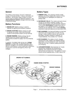
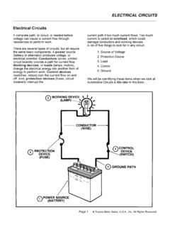
Transcription of Section 5 The Charging System
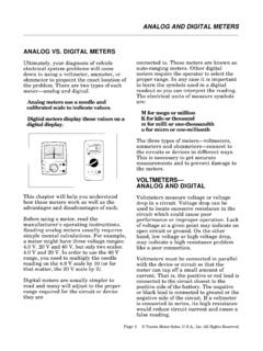
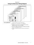
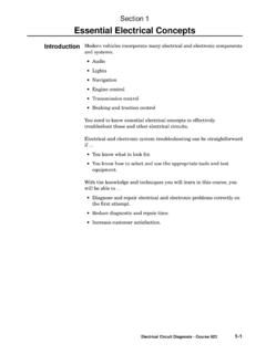
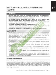
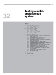
1 electrical Circuit Diagnosis - Course 6235-1 The Charging System has two essential functions: Generate electrical power to run the vehicle's electrical systems Generate current to recharge the vehicle's batteryElectrical power - At low engine speeds, the battery may supplysome of the power the vehicle needs. At high engine speeds, thecharging System handles all of the vehicle's electrical - Alternator (generator) output is higher than batteryvoltage to recharge the SystemThe alternator suppliespower for the vehiclewhen the engine isrunning and engine speedis above 5-01TL623f501 Section 5 The Charging SystemChargingSystemSection 55-2 TOYOTA Technical TrainingThese components make up the Charging System : Alternator Voltage regulator Battery Charging indicatorCharging SystemComponentsThis figure shows themajor components of thecharging 5-02TL623f500 Charging SystemComponentsThe Charging SystemElectrical Circuit Diagnosis - Course 6235-3 The alternator contains these main components.
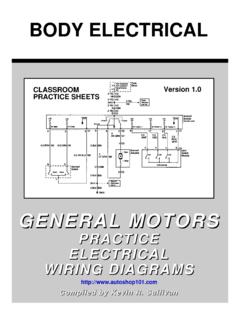
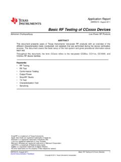
2 Stator (attached to alternator housing, remains stationary) Rotor (spins inside the stator) Rectifier Voltage regulatorSlip rings and brushes make an electrical connection to the spinning alternator generates electricity through these steps: Engine power drives the alternator rotor through a pulley anddrive belt. The alternator rotor spins inside the windings of the stator. The stator windings generate an alternating current. Rectifier diodes change the alternating current (AC) into directcurrent (DC).AlternatorExploded view of thealternator s 5-03TL623f503 AlternatorSection 55-4 TOYOTA Technical TrainingThe voltage regulator controls the alternator's output current to preventover- Charging and under- Charging of the battery. It does this byregulating the current flowing from the battery to the rotor's field 's IC voltage regulator is a fully electronic device, using resistorsand RegulatorThe voltage regulatorcontrols the alternator soutput 5-04TL623f504 Voltage RegulatorThe Charging SystemElectrical Circuit Diagnosis - Course 6235-5 The battery supplies current to energize the alternator field coil.
3 Thebattery also acts as a voltage stabilizer. The battery must alwaysremain attached to the electrical System while the engine is battery suppliescurrent to energize thealternator s field 5-05TL623f505 BatterySection 55-6 TOYOTA Technical TrainingThe Charging indicator is usually an ON/OFF warning lamp. When thesystem is running, the light should be OFF. The lamp lights when thecharging System is not providing sufficient Charging indicatorlights when the chargingsystem is not supplyingenough power to chargethe 5-06TL623f506cCharging IndicatorThe Charging SystemElectrical Circuit Diagnosis - Course 6235-7 Current in the Charging System changes for these three differentoperating conditions: Ignition switch to ON - engine stopped Ignition switch to ON - engine running alternator output belowdesired voltage Ignition switch to ON - engine running alternator output abovedesired voltageIgnition switch to ON - engine stopped: As soon as the ignition switch is turned to ON, the IC regulatorcauses a current of about amps through the rotor's field coil.
4 The IC regulator turns on the Charging indicator. There is no output from the stator because the rotor is not Switchto ON - EngineStoppedThe IC regulator causes asmall current through thealternator rotor field 5-07TL623f507cCharging SystemOperationSection 55-8 TOYOTA Technical TrainingIgnition switch to ON - engine running, alternator outputbelow desired voltage: The windings in the stator generate a voltage any time the rotor isenergized and spinning. Voltage generated in the stator is applied to the voltage regulator. If the alternator output voltage is below volts, the voltageregulator responds by increasing current through the field coil ofthe rotor. This causes the voltage to increase. A Charging current is sent to the ON- Output VoltageBelow voltsThe windings in the statorgenerate a voltage, and acharging current is sentto the 5-08TL623f508cThe Charging SystemElectrical Circuit Diagnosis - Course 6235-9 Ignition switch to ON - engine running alternator outputabove desired voltage:When the voltage regulator senses alternator output at or above volts: It reduces current through the rotor field coil.
5 This reduces alternator output voltage. No Charging current goes to the ON- OutputVoltage HighThe regulator reducescurrent through the fieldcoil; no Charging currentgoes to the 5-09TL623f509cSection 55-10 TOYOTA Technical TrainingSafeguards are built into the alternator in case the connection toTerminal B or Terminal S is lost: Terminal S is an input to the regulator to monitor voltage levels. Terminal B is alternator S disconnected: The voltage regulator does not detect voltage. The voltage regulator regulates voltage at Terminal B to 16 voltsand lights the Charging SDisconnectedThe voltage regulatorregulates voltage atTerminal B to 16 voltsand lights thecharging 5-10TL623f510cThe Charging SystemElectrical Circuit Diagnosis - Course 6235-11 Terminal B disconnected: No Charging voltage available for battery. This condition could result in voltage regulator BDisconnectedAn open circuit in theB terminal results in nocharging output forthe battery andcould damage thevoltage 5-11TL623f511cSection 55-12 TOYOTA Technical TrainingThe Charging System requires little maintenance.
6 The battery shouldbe fully charged and connections kept clean and of Charging System problems is typically may be electrical or troubleshooting flow diagram on the next page lists the mostcommon Charging System problems, the possible cause, andrecommended actions to resolve the with a thorough visual inspection. If this fails to turn up thepossible cause, several tests are available to help you find the problem: Alternator output test (no load) Alternator output test (with load) Voltage drop tests Charging current relay test Diode testsDiagnosisand TestingThe Charging SystemElectrical Circuit Diagnosis - Course 6235-13 Use this flow diagram to troubleshoot Charging systems with compact,high speed DiagramFig. 5-12TL623f512 TroubleshootingFlow DiagramSection 55-14 TOYOTA Technical TrainingInclude the following items in a visual inspection of the Charging System :1.
7 Battery2. Fusing3. Alternator Drive Belt4. Alternator Wiring5. Noise6. Charging IndicatorItem 1: BatteryInspect the battery forthe defects shownin this 5-13TL623f513cCharging SystemVisual InspectionThe Charging SystemElectrical Circuit Diagnosis - Course 6235-15 Other Battery ChecksState of Charge - Check the specific gravity of the electrolyte todetermine the battery's state of charge. Specific gravity should be between and (at 80 C).Condition - Check overall battery condition with a battery BatteryChecksA hydrometer can tellyou the battery s stateof 5-14TL623f514 Section 55-16 TOYOTA Technical TrainingItem 2: Fusing Refer to the EWD to identify fuses and fusible links in the chargingsystem for the vehicle under test. Check these components for 2: FusingFusible links must be partof the visual inspection ofthe Charging 5-15TL623f515 The Charging SystemElectrical Circuit Diagnosis - Course 6235-17 Item 3: Alternator Drive Belt Good condition Correct alignment Proper tensionItem 3: Alternator Drive BeltAlternator drive belts must be ingood condition and be properlyaligned and 5-16TL623f516cSection 55-18 TOYOTA Technical TrainingItem 4: Alternator Wiring Make sure all connections are clean and tight.
8 Check wiring for frayed insulation and other physical 4:Alternator WiringInspect wires andconnections atthe 5-17TL623f517 The Charging SystemElectrical Circuit Diagnosis - Course 6235-19 Item 5: Alternator NoiseListen for any unusual noise while the alternator is operating: Squealing may indicate a bearing problem or a worn or improperlytensioned and adjusted drive belt. Hissing may be a sign that one or more of the diodes are defective,because of a pulsating magnetic field and 5:Alternator NoiseAlternator noise may beimportant in diagnosingpotential 5-18TL623f518 Section 55-20 TOYOTA Technical TrainingItem 6: Charging Indicator Indicator lights with ignition ON and engine not running. Indicator goes off with engine the indicator does not operate as described above, refer to theappropriate EWD and check the indicator 6:ChargingIndicatorThe Charging indicatorshould be on with theignition on and the enginenot running and off withthe engine 5-19TL623f519cThe Charging SystemElectrical Circuit Diagnosis - Course 6235-21 Use the following steps to perform the test with a Sun VAT-40 or VAT-60tester:1.
9 Set the tester's Load control to Connect the tester leads. Red lead to positive terminal. Black lead to negative terminal. Clamp the ammeter clamp-on probe onto the battery's ground Set the tester's voltage range to the appropriate Zero both meters on the tester, if Turn the ignition switch to ON (do not start the engine).Alternator OutputTest (No Load)A VAT-40 Battery Testeris connected for the noload output 5-20TL623f520cAlternator OutputTest (No Load) Section 55-22 TOYOTA Technical Training6. Record the ammeter reading. This is the discharge current (typically about 6 amps). Alternator must supply this amount of current before it canprovide Charging current to the Start the engine and adjust engine speed to about 2,000 Allow engine to warm up for 3 to 4 Record the ammeter reading. Add the discharge current (from Step 4) to the reading now onthe ammeter.
10 The total should be less than 10 amps. The battery may not have been fully charged if the total currentis more than 10 amps. Monitor the ammeter; the reading shoulddecrease as the battery Record the voltmeter reading. The voltmeter reading should be within specification for thealternator during the entire test. This value is typically between13 and 15 volts; refer to the appropriate service manual for thecorrect specification. If the voltmeter reading is higher than specified, the voltageregulator is probably defective. Replace the regulator if possibleor replace the alternator. If the voltmeter reading is lower than specified, the cause couldbe a bad regulator or a fault in the alternator windings. Replacethe alternator if it has an internal voltage regulator. For alternators with externally mounted regulators, confirm thecause by grounding Terminal F on the alternator.