
cp2102rev1 0 - SparkFun Electronics
Option 1: A 4.7 kΩ pull-up resistor can be added to increase noise immunity. Option 2: A 4.7 µF tantalum capacitor can be added if powering other devices from the on-chip regulator. Option 3: Avalanche transient voltage suppression diodes should be added for ESD protection. Option 3: Use Littlefuse p/n SP0503BAHT or equivalent. 1 CP2102 ...
Download cp2102rev1 0 - SparkFun Electronics

Information
Domain:
Source:
Link to this page:
Documents from same domain
AT Commands Reference Guide - SparkFun …
www.sparkfun.comAT Commands Reference Guide 80000ST10025a Rev. 0 - 04/08/06 Reproduction forbidden without Telit Communications S.p.A. written authorization - All …
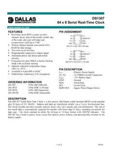
DS1307 64 x 8 Serial Real-Time Clock
www.sparkfun.com1 of 12 100101 FEATURES Real-time clock (RTC) counts seconds, minutes, hours, date of the month, month, day of the week, and year with …

Advanced User Manual - SparkFun Electronics
www.sparkfun.comusage information and a summary of common commands refer to the Install Guide for a given product. Version 4.77 August 27, 2009 Roving Networks reserves the right to make corrections, modifications, and changes to its products, documentation and services ... Advanced User Manual.

Preliminary Product Specification v1 - SparkFun Electronics
www.sparkfun.comRevision 1.0 Page 3 of 75 nRF24L01+ Preliminary Product Specification Writing Conventions This product specification follows a set of typographic rules that make s the document consistent and easy

Single chip 2.4 GHz Transceiver nRF24L01
www.sparkfun.comPRELIMINARY PRODUCT SPECIFICATION nRF24L01 Single Chip 2.4 GHz Radio Transceiver Nordic Semiconductor ASA - Vestre Rosten 81, N-7075 Tiller, Norway - Phone +4772898900 - …
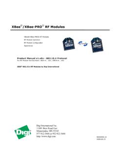
XBee /XBee-PRO RF Modules - SparkFun Electronics
www.sparkfun.comThe XBee®/XBee-PRO® RF Module was designed to mount into a receptacle (socket) and there-fore does not require any soldering when mounting it to a board. The XBee Development Kits con-tain RS-232 and USB interface boards which use two 20-pin receptacles to receive modules.

GSM/GPRS Module - SparkFun Electronics
www.sparkfun.comThis document gives an overview of the LinkSprite GSM/GPRS module: a miniature, single-side board, quad-band GSM 850/EGSM 900/DCS 1800/PCS 1900 module, ready for integration in various kinds of Fix wireless phones and other wireless devices.

16-Channel Constant-Current LED Driver
www.sparkfun.comA6282 Description The A6282 device is designed for LED display applications. This CMOS device includes an input shift register, accompanying data latches, and 16 MOS constant current sink drivers.

+3.3V Low Power Half-Duplex RS-485 Transceivers with ...
www.sparkfun.com10/15/02 SP3481/3485 Low Power Half-Duplex RS485 Transceivers © Copyright 2000 Sipex Corporation 2 SPECIFICATIONS T AMB = T MIN to T MAX and V CC = +3.3V ± 5% ...
XBee /XBee-PRO RF Modules - SparkFun Electronics
www.sparkfun.comDigi International Inc. 11001 Bren Road East Minnetonka, MN 55343 877 912-3444 or 952 912-3444 http://www.digi.com XBee®/XBee-PRO® RF Modules XBee®/XBee-PRO® RF ...
Related documents

www.i-enet
cdn-shop.adafruit.comand power reverse polarity, series a not more than 100ohm resistor at the po-wer supply pin(VDD). The capac-itance 104 as bypass capacitor. To prevent the reflection and hot-swap protection, we suggest to connect a 33 ohm resistor at the data input or output port for impedance. 2.power supply is 12V with 3 LED and constant current(18.5mA ...
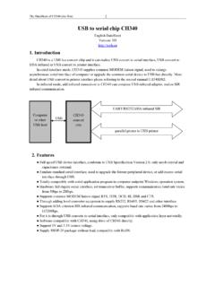
USB to serial chip CH340 - SparkFun Electronics
cdn.sparkfun.comresistor internal, low level is SIR infrared serial interface, high level is common serial interface CKO. OUT(NC.) CH340T: clock output 1 NC CH340R:unconnected, must be suspend 5. Function description CH340 chip set up USB pull-up resistor internal, UD+ and UD- pins must be connected to USB bus directly.

ES9038Q2M 32-Bit Stereo Low Power Audio DAC Analog ...
www.esstech.com• In reset state, a 120k ohm resistor connects between SW and GPIO2 allowing GPIO2 to switch input of SABRE9602. See Register 39: General Configuration 2 for more information. 17 GPIO1 I/O Tri-stated General purpose input/output pin 1, or SPDIF Input 4. 18 DATA2 I Tri-stated DSD Data2 (R) or PCM Data CH1/CH2 or SPDIF Input 2 19 DATA1 I/O Tri ...
Future Technology Devices International Ltd FT232R USB ...
www.ftdichip.comSingle chip USB to asynchronous serial data transfer interface. Entire USB protocol handled on the chip . No USB specific firmware programming required. Fully integrated 1024 bit EEPROM storing device descriptors and CBUS I/O configuration. Fully integrated USB termination resistors.
Altera DE0 Board - Intel
www.intel.comOne 8-Mbyte Single Data Rate Synchronous Dynamic RAM memory chip Supports 16-bits data bus Flash memory 4-Mbyte NOR Flash memory Support Byte (8-bits)/Word (16-bits) mode ... Uses a 4-bit resistor-network DAC With 15-pin high-density D-sub connector Supports up to 1280x1024 at 60-Hz refresh rate . DE0 User Manual 7

SURFACE MOUNT RESISTORS TECHNICAL GUIDE Ver
www.mouser.comchip resistor (by kind) are shown in Fig.8. Fig.8. System figure of thick-film chip resistor The range of resistance value and TCR of thin-film chip resistor (by kind) are shown in Fig.9. Fig.9. System figure of thin-film chip resistor The range of resistance value and TCR of thin-film chip resistor (by kind) are shown in Fig.10. Fig.10.

CAT4016 - 16-Channel Constant Current LED Driver
www.onsemi.comcurrents are programmed together via an external RSET resistor. Low output voltage operation on the LED channels as low as 0.4 V (for 2 to 100 mA LED current) allows for more power efficient designs. A high−speed 4−wire serial interface of up to 25 MHz clock frequency controls each individual channel using a shift register and latch ...
USB hardware and PCB guidelines using STM32 MCUs ...
www.st.comPull-up resistor on USB_DP line Embedded 1.5 kΩ resistor should be added LPM X - X BCD X - ADP - 1. X: supported. 2. Bidirectional, including EP0. 3. When the CAN peripheral is used, only the first 768 bytes are available to USB, the last 256 Bytes are used by CAN. 4.