
Electrical Safety Testing Reference Guide
Feb 28, 2001 · Ground Continuity 13 Ground Bond 13 Product Safety Tests 14 Dielectric Strength Tests 14 ... Tester Environment 26 Operator Training 28 Testing Guidelines/Procedures 28 ... 1. Dielectric Withstand (Hipot) Tests 2. Insulation Resistance Tests 3. Leakage Current Tests 4. Ground Continuity Tests
Download Electrical Safety Testing Reference Guide

Information
Domain:
Source:
Link to this page:
Documents from same domain
Electrical Safety Testing Reference Guide - psma.com
www.psma.comFeb 28, 2001 · 4 Preface 3 Overview 5 Product Safety 5 Electrical Shock 5 Worldwide Regulatory Compliance 6 United States 6 Canada 7 European Union 7 Typical Product Safety Standards 9

Lead-Free LEAD Soldering Guide - psma.com
www.psma.comJul 01, 2006 · Table of Contents Introduction 1 Legislation Update 2 Patent Situation 4 Lead-Free Alloy Tolerances Chart 5
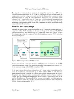
Nominal 48 V input range - psma.com
www.psma.comWide Input Voltage Range in DC Systems (Rev 3) Dave Cooper Page 3of 5 August, 2006 must vary over the 4:1 range, leading to very high peak currents and reduced efficiency.

Major Film Capacitor Dielectrics - psma.com
www.psma.comHCPP is high crystalline polypropylene Rough PP is polypropylene with a roughened surface PPS is polyphenylene sulfide This slide shows common films used as dielectrics in capacitors in the early part of the 21st century. It shows some of the common ... Segmented film …
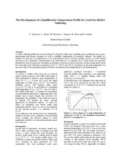
The Development of a Qualification Temperature Profile for ...
www.psma.comThe Development of a Qualification Temperature Profile for Lead-free Reflow Soldering V. Kirchner, C. Klein, M. Beintner, I. Brauer, R. Holz and H. Feufel ... To achieve a reliable solder joint the conventional reflow soldering process with SnPb solder paste is

POWER CONVERTER TOPOLOGY TRENDS - PSMA
www.psma.com8 “Mainstream” Converter Topologies Non-Isolated 1. Boost 4. 2. Buck-Boost 5. 3. Buck 6. Isolated Flyback Forward Push-Pull 7. Half Bridge 8. Full Bridge. Power levels numbers for general . discussion only. Exceptions aplenty.
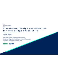
Transformerdesignconsideration forFull Bridge PhaseShift
www.psma.comMar 17, 2020 · produce an increment in the conduction losses in every component through a circulating current. For the magnetizing current, the effect is the same. The ideal design will have low magnetizing current, and the leakage inductance integrated in the operation for achieving ZVS without additional inductances. PAGE 19

Design Considerations for Power Supplies in High-Altitude ...
www.psma.comDesign Considerations for Power Supplies in High-Altitude Applications Kevin Parmenter, VP of Applications, USA, Excelsys Technologies. Altitude Environments in Power Applications Effects of Altitude on Power Electronics Regulatory …
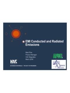
IS97 EMI Conducted and Radiated Emissions - psma.com
www.psma.com(IEEE TRANSACTIONS ON POWER ELECTRONICS, VOL. 29, NO. 4, APRIL 2014 , Comparison and Reduction of Conducted EMI in SiC JFET and Si IGBT-Based Motor Drives Xun Gong, Member, IEEE, and Jan Abraham Ferreira, Fellow, IEEE) ADVANCED MATERIALS -THE KEY TO PROGRESS 15.01.2016 Seite 4
Related documents
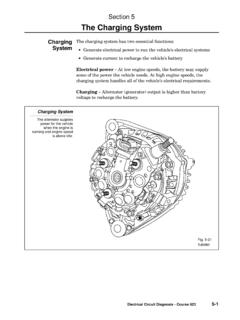
Section 5 The Charging System - Autoshop 101
www.autoshop101.comtester: 1. Set the tester’s Load control to OFF. 2. Connect the tester leads. •Red lead to positive terminal. •Black lead to negative terminal. •Clamp the ammeter clamp-on probe onto the battery’s ground cable. 3. Set the tester’s voltage range to the appropriate setting. 4. Zero both meters on the tester, if needed. 5.
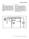
CHARGING SYSTEMS
www.autoshop101.com1. Prepare the tester: • Rotate the Load Increase control to OFF, • Check each meter's mechanical zero. Adjust, if necessary. • Connect the tester Load Leads to the battery terminals; RED to positive, BLACK to negative. • Set Volt Selector to INT 18V. • Set Test Selector to #2 CHARGING. • Adjust ammeter to read ZERO using the electrical
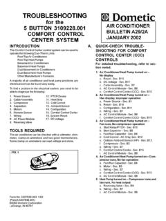
for the 5 BUTTON 3109228.001 AIR CONDITIONER COMFORT ...
bryantrv.comTION as 1 15 volt s may be present. If no voltage is present, the problem is in the coach wiring or breaker/fuse box. 2. CABLE ASSEMBL Y ... Use an ohmmeter to check for continuity through the over-load device. If no continuity is found and the compressor is ... 1) compressor run capacitor 2) compres-sor start capacitor and 3) fan/blower ...

Photovoltaic System Commissioning and Testing
www.mavetech.netSolarlinkTM connectivity between the PV150 tester and Solar Survey 200R irradiance meter, ... 5.1 Continuity Testing 20 5.2 Polarity Testing 23 5.3 Voltage and Current Testing 24 5.3.1 Open-Circuit Voltage Testing 25 5.3.2 Short-Circuit Current Testing 25 5.4 Insulation Resistance Testing 26

ohannesburg - HellermannTyton
www.hellermanntyton.co.zawibre100 voltage tester 24 instruments 1. what is an electrical installation? 1 2. who is responsible? 1 3. how can a layman know if the installation is safe? 1 4. where to obtain a certificate of compliance? 1 5. what must be done before issuing a certificate of compliance? 1 6. what electrical test must be carried out? 1 tests to be done 7 ...

How to Use a Multimeter - learn.sparkfun
learn.sparkfun.comset the knob where the V has a straight line. AC voltage (like what comes out of the wall) can be dangerous, so we rarely need to use the AC voltage setting (the V with a wavy line next to it). If you're messing with AC, we recommend you get a non-contact tester rather than use a digital multimeter. Page 9 of 36

Manual-Ranging Digital Meter
data.kleintools.com9V 10mV ±(1.0% + 2 digits) 1.5V 10mV ±(1.0% + 2 digits) • Diode Test: Approx. 1mA, open circuit voltage 2.0V DC • Continuity Check: Audible signal <100Ω • Battery Test: 9V (6mA); 1.5V (100mA) • Sampling Frequency: 2 samples per second • Overload: "OL" indicated on display, overload protection 600V RMS in all settings

TESTING FOR VOLTAGE DROP
drivcat.com1 TESTING FOR VOLTAGE DROP Federal-Mogul Document #1519 This test checks for voltage being lost along a wire, or through a connection or switch. Similar results cannot reliably be obtained through the use of continuity testing with an Ohmmeter. Multi-strand wires
ELECTRONIC MEASUREMENT & INSTRUMENTATION LAB LAB …
ggnindia.dronacharya.infoConditioning and Conversion Section along with Display; and a Continuity Tester. Rotary Switches are provided for the Function, Range and Decimal Selection. ... (1) Voltage (2) Current (3) Resistance(4) and Frequency (5). Fig:2 Block diagram of digital multimeter
Table of Contents
csr.innova.comintroduction 1 safety precautions / warnings 2 controls and indicators 4 preparation and caution before use 5 testing procedures 6 a. ac/dc voltage measurement 6 b. resistance measurement w (ohms) 6 c. diode test 7 d. continuity test 8 e. ac/dc current measurement (amps) 8 f. battery test 10 battery and fuse replacement 11