
Engineering Design Representation
the most popular format for design documentation. Automated extraction techniques allow mechanical drawings to be developed directly from 3D geometric models, simplifying the process. However, some elements of design representation not easily conveyed through the model database and therefore not as easily extracted to 2D drawings.
Download Engineering Design Representation

Information
Domain:
Source:
Link to this page:
Documents from same domain
S. L. ten Cate 08-2015 - University of Florida
mae.ufl.eduThe most common types of pipe thread are: • NPT - American Taper Pipe Thread = National Pipe Taper • NPTF - American Taper Pipe Thread for Dryseal joint without sealant compound = National Pipe Taper Fuel NPT and NPTF appear to be identical. Both have the same pitch diameter at the top of the hole of the internal thread or end of the pipe ...

Fundamental Principles of Mechanical Design
mae.ufl.eduMechanical Design Fundamentals K. Craig 20 Laws of Nature • To develop a physical model of an existing system or of a system concept, we use engineering judgment and make simplifying assumptions. • To develop a mathematical model, a model that can predict system dynamic behavior, we apply the Laws of Nature to the physical model.
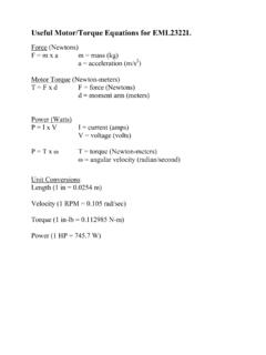
Useful Motor/Torque Equations for EML2322L
mae.ufl.eduCalculate the Torque required to lift the Force with the lever arm . T = F x d = 49.05 N x 0.5 m = 24.525 N-m . We cannot perform the lift with this set-up, because the stall torque is smaller than . the torque required for the lift. We must either shorten the length of the lever arm,
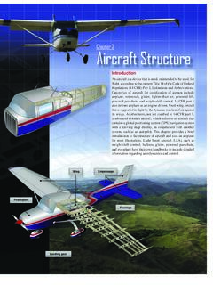
Chapter 2 Aircraft Structure
mae.ufl.edustructure constructed of wood, steel, or aluminum tubing. [Figure 2-5] The most popular types of fuselage structures used in today’s aircraft are the monocoque (French for “single shell”) and semimonocoque. These structure types are discussed in more detail under aircraft construction later in the chapter. Wings

Drive Wheel Motor Torque Calculations
mae.ufl.eduDrive Wheel Motor Torque Calculations . Step Four: Determine Total Tractive Effort . The Total Tractive Effort (TTE) is the sum of the forces calculated in steps 1, 2, and 3. (On higher speed vehicles friction in drive components may warrant the addition of 10%-15% to the total tractive effort to ensure acceptable vehicle performance.)
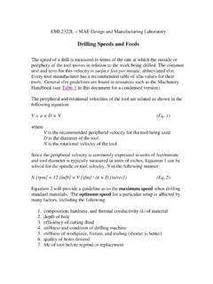
Drilling Speeds and Feeds - University of Florida
mae.ufl.eduEquation 2 will provide a guideline as to the maximum speed when drilling standard materials. The optimum speed for a particular setup is affected by many factors, including the following: 1. composition, hardness, and thermal conductivity (k) of material 2. depth of hole 3. efficiency of cutting fluid 4. stiffness and condition of drilling ...

CHAP 4 FINITE ELEMENT ANALYSIS OF BEAMS AND FRAMES
mae.ufl.edu1 CHAP 4 FINITE ELEMENT ANALYSIS OF BEAMS AND FRAMES 2 INTRODUCTION • We learned Direct Stiffness Method in Chapter 2 – Limited to simple elements such as 1D bars • we will learn Energy Methodto build beam finite element – Structure is in equilibrium when the potential energy is minimum

Engineering Change Notice - University of Florida
mae.ufl.eduEngineering Change Notice Definition . An . Engineering Change Notice (ECN) is a document authorizing and recording design changes throughout the prototyping and life-cycle phases of a product. ECN documentation contains the ... The drawings must clearly show the detail(s) affected by the change. ...
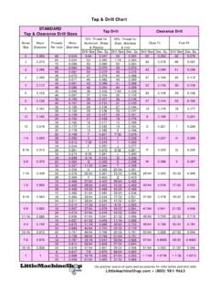
Tap & Drill Chart
mae.ufl.eduDrill Size Dec. Eq. Drill Size Dec. Eq. Drill Size Dec. Eq. Drill Size Dec. Eq. 0 0.060 80 0.045 3/64 0.047 55 0.052 52 0.064 50 0.070 64 0.054 53 0.060 1/16 0.063

EML 2322L – MAE Design and Manufacturing Laboratory ...
mae.ufl.eduEML 2322L – MAE Design and Manufacturing Laboratory . Dimensioning Rules . 1. Each dimension should be given clearly so it can be interpreted in only one way. 2. Dimensions should not be duplicated or the same information given in …
Related documents
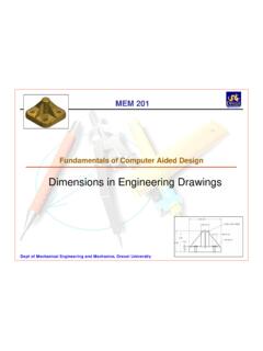
Fundamentals of Computer Aided Design
www.pages.drexel.edu13. Inch drawings do not include a preceding zero for dimensions less than one. For example, use .50 to indicate 1/2 inch. Metric dimensions require a …
Composite Slabs and Beams using Steel Decking: Best ...
www.steelconstruction.infoThe design of composite slabs and beams is discussed in detail in relation to the Eurocodes and BS 5950. In addition to general ultimate and serviceability limit state design issues, practical design considerations such as the formation of holes in the slab, support details, fire protection, and attachments to the slab are discussed. Guidance is

STRUCTURE DESIGN - DESIGN MANUAL LIST OF FIGURES
connect.ncdot.gov2 DESIGN DATA 2-1 Seismic Zone – LRFD Bridge Design Specifications 2-2 Soil Profile Types 2-3 Design Traffic Lane 3 MATERIAL 4 PRELIMINARY DRAWINGS 4-1 Example Preliminary General Drawing (Sheet 1 of 2) 4-2 Example Preliminary General Drawing (Sheet 2 of 2) 4-3 Construction Limits Sketches for Bridges and Culverts
Engineering Design and Construction Manual for …
vpa.vic.gov.auThis Engineering Design and Construction Manual outlines a series of shared . engineering standards and specifications, prepared by the GAA, the municipalities of Casey, Cardinia, Hume, Melton, Whittlesea and Wyndham and the Office of Local ... definition Approval shall mean drawings having been stamped with Council’s approval stamp and ...

REQUIRED INFORMATION AND DRAWINGS
www.health.ny.govDrawings separated and labeled per "NYSDOH AND DASNY ELECTRONIC DRAWINGS SUBMISSION GUIDANCE FOR CON REVIEWS" Size limit does not exceed 100 MB. -- PDF that is produced by saving files electronically. Scanned drawings are not accepted. - - Site Plan (SP100) -- Life Safety Plans (LSC 100) -- Schedules (A000) N/R
Engineering Drawings: Dimensioning - University of Sydney
web.aeromech.usyd.edu.auMicrosoft PowerPoint - Engineering Drawings Lecture Dimensioning Author: Paul Created Date: 5/28/2014 12:15:11 AM ...

Engineering Drawings: Sectioning - University of Sydney
web.aeromech.usyd.edu.audrawings in this THE FULL SECTIONAL VIEW the d FIGURE 3.10 ALIGNED SECTIONS In to detail a plane, a is 12 an eric of a which cut and apart. The detail of along of cut is of A d a side Y in 12. out-ting IS by A-A of the plane A-A whlch the is 3.11 in b2th . FIGURE 3.12 FIGURE 3.13