
Experiment 2 Basic Logic Gates Implementation Using ...
rows that are connected to the power supply, holes in the first row for logic 0 and holes in the second row for logic 1. Figure 4 5. You can determine the output using the logic probe, logic probe as shown in (Figure5) is a hand-held pen-like probe used for analyzing and troubleshooting the logical states (Boolean 0 or 1) of a digital circuit.
Download Experiment 2 Basic Logic Gates Implementation Using ...

Information
Domain:
Source:
Link to this page:
Documents from same domain

Lab 0: Introduction to Networks lab
engineering.ju.edu.joNetwork Layer (Layer 3) The main function of this layer is routing data has to its intended destination on the network as long as there is a physical network connection. The device that allows us to accomplish this spectacular feat is the router, sometimes referred to as a Layer 3 device. While doing so, it has
Related documents

LADDER LOGIC - Sharif
ee.sharif.eduLADDER LOGIC "Ladder" diagrams Ladder diagrams are specialized schematics commonly used to document industrial control logic systems. They are called "ladder" diagrams because they resemble a ladder, with two vertical rails (supply power) and as many "rungs" (horizontal lines) as there are control circuits to represent.

Lecture 21 Power Optimization (Part 2)
classes.engineering.wustl.edu• Generate budgets for power, performance, area • Generate RTL to match system-level model • Select IP blocks • Analyze and optimize power at module level and chip level • Analyze power implications of test features • Check power against budget for various modes • Synthesize RTL to gates using power optimizations
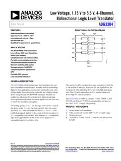
Low Voltage, 1.15 V to 5.5 V, 4-Channel, Bidirectional ...
www.analog.comarchitecture allows the device to perform bidirectional logic level translation without an additional signal to set the direction in which the translation takes place. The voltage applied to V CCA sets the logic levels on the A side of the device, while V CCY sets the levels on the Y side. For proper operation, V CCA 1.must always be less than ...
Logic Level MOSFET or Transistor Interfacing?
www.best-microcontroller-projects.comAs mentioned logic level MOSFETs are FETs with a threshold voltage (VT) of about 1-2V (see the data sheet) and these will work directly with TTL or CMOS logic. The advantage you get is that they draw zero gate current. A typical logic FET is …

EXPERIMENT 3: TTL AND CMOS CHARACTERISTICS
www.classe.cornell.edulogic family, there are several logic series: the 74 standard, 74L low-power, 74H high-speed, 74S standard Schottky, 74LS low-power Schottky series, and 74ALS advanced low-power Schottky series. The TTL family was the most widely used logic family for several years, characterized by its relatively high speed operation.

BSS138 - N-Channel Logic Level Enhancement Mode Field ...
www.onsemi.comN-Channel Logic Level Enhancement Mode Field Effect Transistor BSS138 General Description These N−Channel enhancement mode field effect transistors are produced using onsemi’s proprietary, high cell density, DMOS technology. These products have been designed to minimize on−state resistance while provide rugged, reliable, and fast ...
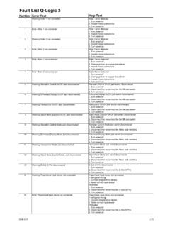
Fault List Q-Logic 3 - Pride Mobility Products Corp.
www.pridemobility.com1. Turn power off 2. Wait 5 seconds 3. Turn power on 53 Warning: Sip N Puff not in neutral position Sip N Puff input operated at power up 1. Turn power off 2. Release Sip N Puff input 3. Turn power on 54 Error: Sip N Puff out of neutral position Sip N Puff input operated at power up 1. Turn power off 2. Release Sip N Puff input 3. Turn power on