Example: bankruptcy
Experiment 2 Basic Logic Gates Implementation Using ...
rows that are connected to the power supply, holes in the first row for logic 0 and holes in the second row for logic 1. Figure 4 5. You can determine the output using the logic probe, logic probe as shown in (Figure5) is a hand-held pen-like probe used for analyzing and troubleshooting the logical states (Boolean 0 or 1) of a digital circuit.
Tags:
Information
Domain:
Source:
Link to this page:
Documents from same domain

Lab 0: Introduction to Networks lab
engineering.ju.edu.joNetwork Layer (Layer 3) The main function of this layer is routing data has to its intended destination on the network as long as there is a physical network connection. The device that allows us to accomplish this spectacular feat is the router, sometimes referred to as a Layer 3 device. While doing so, it has
Related documents
Fault List Q-Logic 3 - Pride Mobility Products Corp.
www.pridemobility.com1. Turn power off 2. Wait 5 seconds 3. Turn power on 53 Warning: Sip N Puff not in neutral position Sip N Puff input operated at power up 1. Turn power off 2. Release Sip N Puff input 3. Turn power on 54 Error: Sip N Puff out of neutral position Sip N Puff input operated at power up 1. Turn power off 2. Release Sip N Puff input 3. Turn power on

Lecture 21 Power Optimization (Part 2)
classes.engineering.wustl.edu• Generate budgets for power, performance, area • Generate RTL to match system-level model • Select IP blocks • Analyze and optimize power at module level and chip level • Analyze power implications of test features • Check power against budget for various modes • Synthesize RTL to gates using power optimizations

EXPERIMENT 3: TTL AND CMOS CHARACTERISTICS
www.classe.cornell.edulogic family, there are several logic series: the 74 standard, 74L low-power, 74H high-speed, 74S standard Schottky, 74LS low-power Schottky series, and 74ALS advanced low-power Schottky series. The TTL family was the most widely used logic family for several years, characterized by its relatively high speed operation.
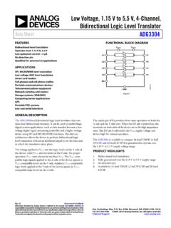
Low Voltage, 1.15 V to 5.5 V, 4-Channel, Bidirectional ...
www.analog.comarchitecture allows the device to perform bidirectional logic level translation without an additional signal to set the direction in which the translation takes place. The voltage applied to V CCA sets the logic levels on the A side of the device, while V CCY sets the levels on the Y side. For proper operation, V CCA 1.must always be less than ...

LADDER LOGIC - Sharif
ee.sharif.eduLADDER LOGIC "Ladder" diagrams Ladder diagrams are specialized schematics commonly used to document industrial control logic systems. They are called "ladder" diagrams because they resemble a ladder, with two vertical rails (supply power) and as many "rungs" (horizontal lines) as there are control circuits to represent.

BSS138 - N-Channel Logic Level Enhancement Mode Field ...
www.onsemi.comN-Channel Logic Level Enhancement Mode Field Effect Transistor BSS138 General Description These N−Channel enhancement mode field effect transistors are produced using onsemi’s proprietary, high cell density, DMOS technology. These products have been designed to minimize on−state resistance while provide rugged, reliable, and fast ...
Logic Level MOSFET or Transistor Interfacing?
www.best-microcontroller-projects.comAs mentioned logic level MOSFETs are FETs with a threshold voltage (VT) of about 1-2V (see the data sheet) and these will work directly with TTL or CMOS logic. The advantage you get is that they draw zero gate current. A typical logic FET is …