Future Technology Devices International Ltd
FTDI FT232B style, asynchronous serial UART interface option with full hardware handshaking and modem interface signals. Fully assisted hardware or X -On / X -Off software handshaking. UART Interface supports 7/8 bit data, 1/2 stop bits, and Odd/Even/Mark/Space/No Parity. Auto -transmit enable control for RS485 serial
Download Future Technology Devices International Ltd

Information
Domain:
Source:
Link to this page:
Documents from same domain

FTDI Drivers Installation Guide for Windows 10
www.ftdichip.comApplication Note 10AN_396 FTDI Drivers Installation Guide for Windows Version 1.0 Document Reference No.: FT_001281 Clearance No.: FTDI# 486
Future Technology Devices ... - FTDI Chip Home Page
www.ftdichip.comCopyright © Future Technology Devices International Limited 1 FT232R USB UART IC Datasheet Version 2.14 Document No.: FT_000053 Clearance No.: FTDI# 38
Future Technology Devices International Ltd - FTDI
www.ftdichip.comFuture Technology Devices International Limited (FTDI) Unit1, 2 Seaward Place, Centurion Business Park,, Glasgow G41 1HH United Kingdom Tel.: +44 (0) 141 429 2777 Fax: + 44 (0) 141 429 2758

Future Technology Devices International Ltd. - FTDI
www.ftdichip.comCopyright © 2015 Future Technology Devices International Limited 18 Document Reference No.: FT_000160 FTDI Drivers Installation guide for Windows 7

USB Hi-Speed Serial/Hub Module - FTDI Chip …
www.ftdichip.comCopyright © Future Technology Devices International Limited 4 Document Reference No.: FT_000331 USB Hi-Speed Serial/Hub Module Version 1.4 Clearance No.: FTDI# 174
Future Technology Devices International Ltd - FTDI
www.ftdichip.comFuture Technology Devices International Limited (FTDI) Unit1, 2 Seaward Place, Centurion Business Park, Glasgow G41 1HH United Kingdom Tel.: +44 (0) 141 429 2777 Fax: + 44 (0) 141 429 2758
Future Technology Devices International Ltd - FTDI
www.ftdichip.comCopyright © Future Technology Devices International Limited 1 FT4232H QUAD HIGH SPEED USB TO MULTIPURPOSE UART/MPSSE IC Datasheet Version 2.5
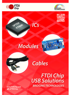
ICs Modules Cables USB Solutions - FTDI
www.ftdichip.comExtensive USB Portfolio Whether your design needs silicon chips, cables, or modules, check out FTDI Chip’s large portfolio of USB and system level products.
Future Technology Devices International Ltd - FTDI
www.ftdichip.comCopyright © 2010 Future Technology Devices International Limited 8 Document No.: FT_000173 FT2232D /FIFO ICDUAL USB TO SERIAL UART Datasheet
Vinculum-II Debug Interface - FTDI
www.ftdichip.com2 Copyright © 2011 Future Technology Devices International Limited Application Note AN_138 Vinculum-II Debug Interface Version 2.0 Document Reference No.: FT000252 Clearance No.: FTDI# 147
Related documents

Paychex TrueShift User Guide
www.trueshifttimeclock.comTable of Contents TOC Paychex TrueShift User Guide Paychex TrueShift User Guide

2.7V 4-Channel/8-Channel 10-Bit A/D Converters with SPI ...
cdn-shop.adafruit.comJan 02, 2008 · FIGURE 1-1: Serial Interface Timing. Power Requirements Operating Voltage VDD 2.7 — 5.5 V Operating Current IDD —425 225 550 µA VDD = VREF = 5V, DOUT unloaded VDD = VREF = 2.7V, DOUT unloaded Standby Current IDDS —0.005 2 µACS = VDD = 5.0V Electrical Specifications: Unless otherwise indicated, VDD = +2.7V to +5.5V, VSS =GND.

Attention: WORLD backwards, serial 7s from 100
www.admsep.orgFlight of ideas: Rapid shift from one topic to another. Perseveration: R epetition of a particular response (e.g., word or phrase), regardless of the absence or cessation of a stimulus. Thought blocking: Abrupt cessation of speech without explanation in the middle of a sentence
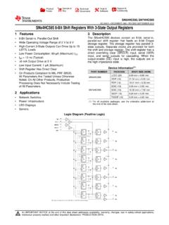
SNx4HC595 8-Bit Shift Registers With 3-State Output ...
www.ti.comThe SNx4HC595 devices contain an 8-bit, serial-in, parallel-out shift register that feeds an 8-bit D-type storage register. The storage register has parallel 3-state outputs. Separate clocks are provided for both the shift and storage register. The shift register has a direct overriding clear (SRCLR) input, serial (SER)

Introduction • SPI Pin Functionality Features
ww1.microchip.comThe SPI consists of four different signal lines. These lines are the shift clock (SCK), the Master Out Slave In line (MOSI), the Master In Slave Out line (MISO) and the active low Slave Select line ( SS). When the SPI is enabled, the data direction of the MOSI, MISO, SCK, and SS pins are overridden according to the following table. Table 1-1.
8-bit serial-in, serial or parallel-out shift register ...
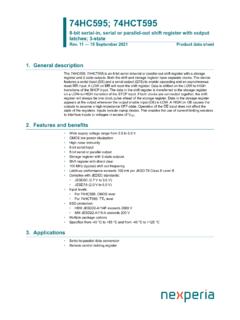
assets.nexperia.comThe 74HC595; 74HCT595 is an 8-bit serial-in/serial or parallel-out shift register with a storage register and 3-state outputs. Both the shift and storage register have separate clocks. The device features a serial input (DS) and a serial output (Q7S) to enable cascading and an asynchronous reset MR input. A LOW on MR will reset the shift register.

Chapter 6 Synchronous Sequential Circuits
my.ece.utah.eduout = 1 , R 1 in = 1 , Done = 1 w = 0 w = 1 C ⁄ R 1 out = 1 , R 2 in = 1 B ⁄ R 2 out = 1 , R 3 ... Block diagram for the serial adder. Sum = A + B Shift register Shift register Adder FSM Shift register B A a b s Clock . G H (⁄ state . adder
Serial Peripheral Interface (SPI) - College of Engineering
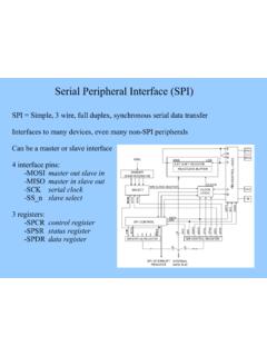
web.engr.oregonstate.eduSerial Peripheral Interface (SPI) Full duplex, synchronous serial data transfer Data is shifted out of the master's (mega128) MOSI pin and in it's MISO pin Data transfer is initiated by simply writing data to the SPI data register. All data movement is coordinated by SCK. Slave select may or may not be used depending on interfacing device.