FX Programming Manual.
Note’s on the Symbols used in this Manual At various times through out this manual certain symbols will be used to highlight points of information which are intended to ensure the users personal safety and protect the integrity of equipment. Whenever any of the following symbols are encountered its associated note must be read and understood.
Download FX Programming Manual.

Information
Domain:
Source:
Link to this page:
Documents from same domain
HF-KN/HF-SN SERVO MOTOR INSTRUCTION …
dl.mitsubishielectric.comA - 3 CAUTION Do not carry the servo motor by holding the cables, shaft, encoder, or connector. Install the servo amplifier and the servo motor in a load-bearing place in accordance with the Instruction
FX COMMUNICATION (RS-232C, RS-485, RS-422) …
dl.mitsubishielectric.comFX communication vi • Under no circumstances will Mitsubishi Electric be liable responsible for any consequential damage that may arise as a result of the installation or use of this equipment.
A800/F800 PLC FUNCTION PROGRAMMING MANUAL
dl.mitsubishielectric.com8 PLC FUNCTION Applicable inverter model 1.1 Applicable inverter model This manual explains the PLC function of the FR-A800 series, FR-A800 Plus series and FR-F800 series. 1.2 Function block diagram The following function blocks explain I/O information flow to and from the inverter in the PLC function.
MR-J2S- A Instruction Manual
dl.mitsubishielectric.comA - 4 CAUTION Do not install or operate the servo amplifier and servo motor which has been damaged or has any parts missing. Provide adequate protection to prevent screws and other conductive matter, oil and other combustible
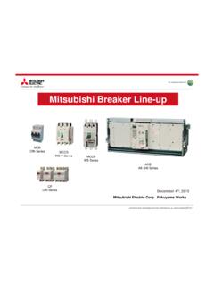
Mitsubishi Breaker Line-up
dl.mitsubishielectric.comelectrical protection, isolation and control products. ... Thailand/Mitsubishi Electric Automation ... IEC 60947-2 up to 800 amp frame size Suitable for isolation Rated current sensitivity ratings: • 30mA • 100/200/500mA selectable Line and Load side are not defined and
FX3S/FX3G/FX3GC/FX3U/FX3UC SERIES PROGRAMMABLE …
dl.mitsubishielectric.comIf an AC power supply is connected to a DC input/output terminal or DC power supply terminal, the ... • Please contact a certified electronic waste disposal company for the environmentally safe recycling and disposal of your device. B-16 ... Programmable Controllers User's Manual [Positioning Control Edition]
FX3GE Series Programmable Controller HARDWARE MANUAL
dl.mitsubishielectric.comMELSEC-Q/L/F Structured Programming Manual (Fundamentals) SH-080782 MODEL CODE: 13JW06 Programming methods, specifications, functions, etc. required to create structured programs. FXCPU Structured Programming Manual [Device & Common] JY997D26001 MODEL CODE: 09R925 Devices, parameters, etc. provided in structured projects of GX Works2. …
HARDWARE MANUAL - MITSUBISHI ELECTRIC Global Website
dl.mitsubishielectric.comEMC The following products have shown compliance through direct testing (of the identified standards below) and design analysis (through the creation of a technical construction file) to the European Directive for Electromagnetic Compatibility (2004/108/EC) when used as directed by the appropriate documentation.
General-Purpose AC Servo
dl.mitsubishielectric.comIf the molded-case circuit breaker or fuse is activated, be sure to remove the cause and secure safety before switching the power on. If necessary, replace the servo amplifier and recheck the wiring. Otherwise, it may cause smoke, fire, or an electric shock.
MR-J2S- A Instruction Manual
dl.mitsubishielectric.cominstructions of both levels because they are important to personnel safety. ... servo motor and regenerative resistor on incombustible material. Installing them ... Install the servo amplifier in a load-bearing place in accordance with the Instruction Manual.
Related documents

Siemens SIMATIC Step 7 Programmer's Handbook
webpageforsivabalan.weebly.com4. Statement List, Ladder Logic, and Function Block Diagram Reference Manuals - These manuals contain both the user’s guide and the reference description of the programming language or representation type. You only require one language type for programming an S7-300/S7-400, but you can mix the languages within a project, if required.

DVP-PLC Application Manual Programming
profsite.um.ac.irthe only difference is that the symbols for the traditional ladder diagram are expressed in the format that are close to its original substance, while those for the PLC ladder diagram employ the symbols that are more explicit when being used in computers or data sheets. In the Ladder Diagram Logics, it could be divided into the Combination Logics

19. STRUCTURED TEXT PROGRAMMING - infoPLC
www.infoplc.netST programs allow named variables to be defined. This is similar to the use of symbols when programming in ladder logic. When selecting variable names they must begin with a letter, but after that they can include combinations of letters, numbers, and some symbols such as ’_’. Variable names
Electrical Symbols and Line Diagrams - University of Florida
abe.ufl.edu2 Line Diagrams A line (ladder) diagram is a diagram that shows the logic of an electrical circuit or system using standard symbols. A line diagram is used to show the relationship between circuits and their components but not the actual location

RSLogix 5 Getting Results Guide - Rockwell Automation
literature.rockwellautomation.comActivities including installation, adjustments, putting into service, use, assembly, disassembly, and maintenance are required to be carried out by

RSLogix 500 Getting Results Guide - Rockwell Automation
literature.rockwellautomation.comActivities including installation, adjustments, putting into service, use, assembly, disassembly, and maintenance are required to be carried out by

Instrumentation and Control - Energy
www.energy.govFigure 7. Simple ladder diagram 24 Figure 8. Sample circuit 25 Figure 9. Relay logic circuit 25 Figure 10. Continuous circuit 26 Figure 11. Ladder diagram for a load device 27 Figure 12. Short circuit 27 Figure 13. Corrected ground fault 28 Figure 14. Electrical signal analysis 29 Figure 15. Gate valve 34 Figure 16. Relief valve 36 Figure 17.
Programmable Logic Controllers 4th Edition (W Bolton)
www.etf.ues.rs.baprogramming methods of ladder, functional block diagram, instruction list, structured text and sequential function chart. w To assist the reader to develop the skills necessary to write programs for programmable logic controllers, many worked examples, multi-choice questions and problems are included in the book with
Project Gutenberg's Tractatus Logico-Philosophicus, by ...
www.gutenberg.orgOct 22, 2010 · Thus, logic has two problems to deal with in regard to Symbolism: (1) the conditions for sense rather than nonsense in combinations of symbols; (2) the condi-tions for uniqueness of meaning or reference in symbols or combinations 7. INTRODUCTION of symbols. A logically perfect language has rules of syntax which pre-