
GENERAL DESCRIPTION
General Specifications GENERAL DESCRIPTION ... BOARD BEND TEST PROCEDURE According to AEC-Q200 BOARD BEND TEST RESULTS ... Soldering Reflow/Wave Reflow/Wave Reflow/Wave WVDC 25V 50V 25V 50V 25V 50V 271 Cap 270 G G 331 (pF) 330 G G J J 471 470 G G J J 681 680 G G J J 102 1000 G G J J J J
Download GENERAL DESCRIPTION

Information
Domain:
Source:
Link to this page:
Documents from same domain
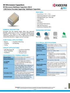
RF/Microwave Capacitors
datasheets.kyocera-avx.comRF/Microwave Capacitors 100B Series Porcelain Superchip® Multilayer Capacitors RF/Microwave Multilayer Capacitors (MLC) GENERAL DESCRIPTION KYOCERA AVX, the industry leader, offers new improved ESR/ESL performance for the 100 B Series RF/Microwave Capacitors. This Series is now available with extended operating temperatures up to 175°C.

RADIAL LEADS - datasheets.kyocera-avx.com
datasheets.kyocera-avx.comNPO typical characteristics, see the KYOCERA AVX Multilayer Ceramic Leaded Capacitors Catalog. STYLE* MAXIMUM CAPACITANCE VALUE C0G (NP0) X7R SR29 900 pF .015 μF SR20 1800 pF .033 μF SR28 SR59 900 pF .015 μF SR13 SR21 1800 pF .033 μF SR30 SR61 SR65 7200 pF .12 μF SR40 SR75.015 μF .27 μF SR22 1800 pF .033 μF SR27 1800 pF .033 …

TAJ – Standard & Low Profile TAJ Series
datasheets.kyocera-avx.com• Entertainment / Infotainment Systems • Height Restricted Design STANDARD CASE DIMENSIONS: millimeters (inches) LOW PROFILE CASE DIMENSIONS: millimeters (inches) XXXXX 227 A LOGO Capacitance Value in pF 227 = 220µF Rated Voltage Code A = 10V ID Code Polarity Band (Anode+) J 1 0 6 Capacitance Value in pF 106 = 10µF Rated Voltage Code …

Automotive MLCC - datasheets.kyocera-avx.com
datasheets.kyocera-avx.com56 Automotive MLCC-NP0 Capacitance Range SIZE 0402 0603 0805 1206 Soldering Reflow/Wave Reflow/Wave Reflow/Wave Reflow/Wave WVDC 25V 50V 25V 50V 100V 200V 25V 50V 100V 200V 250V 25V 50V 100V 200V 250V 500V

PART NUMBER (SEE PAGE 4 FOR COMPLETE PART NUMBER …
datasheets.kyocera-avx.comX7R formulations are called “temperature stable” ceramics and fall into EIA Class II materials. X7R is the most popular of these intermediate dielectric constant materials. Its temperature variation of capacitance is within ±15% from -55°C to +125°C. This capacitance change is …

Low ESR Resin Molded Solid Tantalum Chip, J-Lead TPS ...
datasheets.kyocera-avx.comLow ESR Resin Molded Solid Tantalum Chip, J-Lead Low ESR TPS Series – Standard & Low Profile FEATURES • Low ESR Series of Robust Mn0 2 Solid Electrolyte Capacitors • 100% Surge Current Tested • CV Range: 0.15-1500μF / 2.5-50V • 14 Case Sizes Available • Power Supply Applications APPLICATIONS • General Medium Power DC/DC Convertors
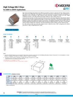
High Voltage MLC Chips
datasheets.kyocera-avx.com95 High Voltage MLC Chips For 600V to 5000V Applications Case Size 0805 1206 1210 1808 1812 Soldering Reflow/Wave Reflow/Wave Reflow Only Reflow Only Reflow Only (L) Length mm 2.10 ± 0.20 3.30 + 0.30 3.30 + 0.40 4.60 + 0.50 4.60 + 0.50

SECTION 2: SOLID CONDUCTIVE POLYMER ELECTROLYTIC …
datasheets.kyocera-avx.comtcj series section 2: solid conductive polymer ... tcjb107m002#0055e b 100 2.5 125 25 6 55 1500 1100 700 400 0 3 tcjb107m002#0070e b 100 2.5 125 25 6 70 1300 900 600 300 1 3 tcjb157m002#0070e b 150 2.5 105 37.5 6 70 1300 900 600 – 3 3 tcjb227m002#0035e b 220 2.5 105 55 8 35 1900 1300 900 – 3 3
Related documents

FlameWheel 450 - dl.djicdn.com
dl.djicdn.comSoldering-iron & wires For connecting ESCspower ’ cables to bottom board. The screw size is M3. Mount the motors using appropriate screws. Note the thread depth and the size of the screws. Using screws that are too long or too large may damage the motor. 19 mm 16 mm 28.2 mm 40 mm 26 mm M6 4×M3 Thread depth 3mm
1-CHIP SERIES
atta.szlcsc.comFeb.12,2019 V.3 www.uniohm.com Page 4/9 Thick Film Chip Resistors –Data Sheet So the resistance value are marked as the following examples 1.96K =196 101 =29B 12.4 =124 10-1 =10X (7) Standard E-24 and not belong to E-96 series values (≤±1%) of 0603 size: the marking is the same as 5% tolerance but marking as underli

BME680 Low power gas, pressure, temperature & humidity …
cdn-shop.adafruit.comprocedure to measure the gas sensor is available in the Application Note: Measurement Instructions for Lab Environment. Referring to Chapter 4, a software solution (BSEC: Bosch Software Environmental Cluster) is available for the BME680. The software is carefully engineered to seamlessly work with the 4-in-1 integrated sensors inside the BME680.
Fast, Voltage-Out, DC to 440 MHz, 95 dB Logarithmic ...
www.analog.comSpecifications subject to change without notice. No ... General Matching Procedure ... Lead Temperature (Soldering 60 sec) 300°C . Stresses above those listed under Absolute Maximum Ratings may cause permanent damage to the device. This is a stress

Site Specific Safety Plan Procedure Form
www.lechase.comOct 17, 2014 · Site Specific Safety Plan Procedure Form. Updated 10.17.14. Procedure Intent: This procedure will: 1. Help identify and document EHS (Environmental, Health, and Safety) issues and/or concerns in the project specifications/bidding process so that Subcontractors will be prepared to provide Contractor with a specific Site Specific Safety Plan. The ...

Fuse Characteristics, Terms and Consideration Factors
www.littelfuse.comconductors, and the use of heat sinks during soldering is often recommended. Lead-Free Soldering Parameters (most instances): Wave Solder — 260ºC, 10 seconds max Reflow Solder — 260ºC, 30 seconds max TEST SAMPLING PLAN: Because compliance with certain specifications requires destructive testing, these tests are

QRE1113, QRE1113GR, QRE1114GR Miniature Reflective …
www.onsemi.com1. Refer to application note AND8003/D, “Storage and Handling of Dry Packed Surface Mounted Devices” for details of handling procedure. 2. Product soldering terminals are silver plated and oxidization may occur with prolonged exposure to ambient environment. Oxidized terminal may have poor solderability performance.

High Stability Thin Film Flat Chip Resistors
www.vishay.comTECHNICAL SPECIFICATIONS ... extensive testing procedure and optical inspection performed on 100 % of the individual chip resistors. This ... soldering using wave, reflow or vapour phase as shown in IEC 61760-1 (1). The encapsulation is resistant to all