Transcription of RF/Microwave Capacitors
1 443RF/Microwave Capacitors100B Series Porcelain Superchip Multilayer CapacitorsRF/Microwave Multilayer Capacitors (MLC)GENERAL DESCRIPTIONKYOCERA AVX, the industry leader, offers new improved ESR/ESL performance for the 100 B Series RF/Microwave Capacitors . This Series is now available with extended operating temperatures up to 175 C. High Density porcelain construction provides a rugged, hermetic APPLICATIONS Bypass Coupling TuningCIRCUIT APPLICATIONS UHF/Microwave RF Power Amplifiers OscillatorsENVIRONMENTAL CHARACTERISTICST hermal ShockMil-STD-202, Method 107, Condition AMoisture ResistanceMil-STD-202, Method 106 Low Voltage HumidityMil-STD-202, Method 103, condition A,with VDC applied while subjected toan environment of 85 C with 85% relative humidity for 240 hoursLife TestMIL-STD-202, Method 108, for 2000 hours, at 125 C. Voltage applied. 200% of WVDC for Capacitors rated at 500 volts DC or less.
2 120% of WVDC for Capacitors rated at 1250 volts DC or less. 100% of WVDC for Capacitors rated above 1250 volts DCTermination StylesAvailable in various surface mount and leaded styles. See Mechanical ConfigurationsTerminal StrengthTerminations for chips and pellets withstand a pull of 5 lbs. min., 15 lbs. typical, for 5 seconds in direction perpendicular to the termination surface of the Case B Size (.110" x .110") Capacitance Range to 1000pF Extended WVDC up to 1500 VDC Low ESR/ESL High Q Low Noise Ultra-Stable Performance High Self-Resonance Established Reliability (QPL)PACKAGING OPTIONSTape & ReelCap Pac (100 pcs)032421 ELECTRICAL SPECIFICATIONST emperature Coefficient (TCC)+90 20 PPM/ C (-55 C to +125 C)+90 30 PPM/ C (+125 C to +175 C)Capacitance to 1000pFOperating Temperature-55 C to +125 C*Quality Factorgreater than 10,000 at 1 MHzInsulation Resistance(IR) pF to 470 pF: 106 Megohms min.
3 @ +25 C at rated WVDC. 105 Megohms min. @ +125 C at rated WVDC. 510 pF to 1000 pF: 105 Megohms min. @ +25 C at rated WVDC. 104 Megohms min. @ +125 C at rated Voltage (WVDC)See Capacitance Values tableDielectric WithstandingVoltage (DWV)250% of WVDC for Capacitors rated at 500 volts DC or less for 5 seconds. 150% of WVDC for Capacitors rated at 1250 volts DC or less for 5 seconds. 120% of WVDC for Capacitors rated above 1250 Volts DC for 5 secondsAging EffectsNonePiezoelectric EffectsNoneCapacitance Drift ( or pF), whichever is greaterRetraceLess than ( or pF), whichever is greater. Impedance Matching DC Blocking Low Noise Amplifiers Filter Networks Timing CircuitsVertical Orientation Tape & Reel rf microwave products The Important Information/Disclaimer is incorporated in the catalog where these specifications came from or available online at by reference and should be reviewed in full before placing any Capacitors100B Series Porcelain Superchip Multilayer CapacitorsRF/Microwave Multilayer Capacitors (MLC)SeriesCase SizeSee mechanical dimensions belowCapacitanceEIA Capacitance Code in two digits = significant figures or R for decimal place.
4 Third digit = number of zeros or after R significant figuresCapacitance Tolerance CodeCodeBCDFGJKMTol..1 pF .25 pF .5 pF 1% 2% 5% 10% 20%HOW TO ORDER910JW100B500 XTCAPACITANCE VALUESCap. CodeCap. (pF) WVDCCap. CodeCap. (pF) WVDCCap. CodeCap. (pF) WVDCCAP. CODECAP. (pF) , C, D500 EXTENDED VOLTAGE20020F, G, J, K, M500 VOLTAGE151150F, G, J, K, , O , C, O , C, J, K, , G, J, K, O = X WVDC SPECIAL VALUES, TOLERANCES, DIFFERENT WVDC AND MATCHING AVAILABLE. ENCAPSULATION OPTION AVAILABLE. PLEASE CONSULT : EXTENDED WVDC DOES NOT APPLY TO CDR T = Tape and Reel, 500 pc qty TV = Vertical Tape and Reel, 500 pc qty Please see last column of mechanical configuration table for other Marking (Optional)Voltage RatingTermination Style CodePlease see 2nd Column Mechanical Configuration Table072022 The above part number refers to a 100 B Series (case size B) 91 pF capacitor, J tolerance ( 5%), 500 WVDC, with W termination (Tin /Lead, Solder Plated over Nickel Barrier), laser marking and Tape and Reel packaging.
5 Rf microwave products The Important Information/Disclaimer is incorporated in the catalog where these specifications came from or available online at by reference and should be reviewed in full before placing any Capacitors100B Series Porcelain Superchip Multilayer CapacitorsRF/Microwave Multilayer Capacitors (MLC)MECHANICAL CONFIGURATIONS eries & Case SizeTerm. CodeMIL-PRF- 55681 Case Size & TypeOutline W/T is a Termination SurfaceBody Dimensions inches (mm)Lead and Termination Dimensions and MaterialPkg TypePkg CodeLength (L)Width (W)Thickness (T)Overlap (Y)Materials100 BWCDR14 BGBS older + .020 - .01( + ).110 .015( ).102 ( ) ( ) .010 ( )Tin / Lead, Solder Plated overNickel Barrier TerminationT&R, 1000 or 500 pcsVertical T&R,1000 or 500 pcsCap Pac, 100 pcsT1K or TTV1K or TVC100100 BPCDR14 BGB + .035 - .01( + ).110 .015( )Heavy Tin/Lead Coated,over Nickel Barrier TerminationT&R, 1000 or 500 pcsVertical T&R, 1000 or 500 pcsCap Pac, 100 pcsT1K or TTV1K or TVC100100 BTN/AB Solderable +.
6 035 - .01( + ).110 .015( )RoHS CompliantTin Plated overNickel Barrier TerminationT&R, 1000 or 500 pcsVertical T&R, 1000 or 500 pcsCap Pac, 100 pcsT1K or TTV1K or TVC100100 BCACDR13 BGB Gold +.020 - .010( + ).110 .015( )RoHS CompliantGold Plated overNickel Barrier TerminationT&R, 1000 or 500 pcsVertical T&R,1000 or 500 pcsCap Pac, 100 pcsT1K or TTV1K or TVC100100 BMSCDR21 BGB .015( ).110 .015( ).120 ( ) (LL )Width(WL )Thickness(TL )Cap Pac, 20 pcsC20100 BARCDR22 BGB Axial ( ) ( ) .005( ).004 .001(.102 .025)Box, 20 or 100 pcsB20 or B100100 BRRCDR24 BGBR adial RibbonLLLWLWTBox, 20 or 100 pcsB20 or B100100 BRWCDR23 BGBR adial .020( ).500 ( )#26 AWG.,.016 (.406) , 20 or 100 pcsB20 or B100100 BAWCDR25 BGBA xial Wire LLWTLBox, 20 or 100 pcsB20 or B100 Additional lead styles available: Narrow Microstrip (NM), Narrow Axial Ribbon (NA) and Vertical Narrow Microstrip (H). Other lead lengths are available; consult leads are high purity silver attached with high temperature solder and are RoHS rf microwave products The Important Information/Disclaimer is incorporated in the catalog where these specifications came from or available online at by reference and should be reviewed in full before placing any MECHANICAL CONFIGURATIONS eries & Case SizeTerm.
7 CodeMIL-PRF- 55681 Case Size & TypeOutline W/T is a Termination SurfaceBody Dimensions inches (mm)Lead and Termination Dimensions and MaterialPkg TypePkg CodeLength (L)Width (W)Thickness (T)Overlap (Y)Materials100 BWNM eets + .020 - .01( + ).110 .015( ).102 ( ) ( ) .010 ( )Tin / Lead, Solder Plated overNickel Barrier TerminationT&R, 1000 or 500 pcsVertical T&R,1000 or 500 pcsCap Pac, 100 pcsT1K or TTV1K or TVC100100 BPNM eets RequirementsB Solderable + .035 - .01( + ).110 .015( )Heavy Tin / Lead, Coated overNon-Magnetic Barrier TerminationT&R, 1000 or 500 pcsVertical T&R,1000 or 500 pcsCap Pac,100 pcsT1K or TTV1K or TVC100100 BTNM eets RequirementsB Non-Mag Solderable +.020 - .010( + ).110 .015( )RoHS CompliantTin Plated overNon-Magnetic Barrier TerminationT&R, 1000 or 500 pcsVertical T&R,1000 or 500 pcsCap Pac, 100 pcsT1K or TTV1K or TVC100100 BMNM eets RequirementsB .015( ).110.
8 015( ).120 ( ) (LL )Width(WL )Thickness(TL )Cap Pac, 20 pcsC20100 BANM eets RequirementsB Axial ( ) ( )( ) .005( ).004 .001(.102 .025)Box, 20 or 100 pcsB20 or B100100 BFNM eets RequirementsBRadial RibbonLLLWLWTBox, 20 or 100 pcsB20 or B100100 BRNM eets RequirementsBRadial .020( ).500 ( )#26 AWG.,.016 (.406) , 20 or 100 pcsB20 or B100100 BBNM eets RequirementsBAxial Wire LLWTLBox, 20 or 100 pcsB20 or B100 Additional lead styles available: Narrow Microstrip (NM), Narrow Axial Ribbon (NA) and Vertical Narrow Microstrip (H). Other lead lengths are available; consult factory. All leads are high purity silver attached with high temperature solder and are RoHS Capacitors100B Series Porcelain Superchip Multilayer CapacitorsRF/Microwave Multilayer Capacitors (MLC)092921 rf microwave products The Important Information/Disclaimer is incorporated in the catalog where these specifications came from or available online at by reference and should be reviewed in full before placing any DATASUGGESTED MOUNTING PAD DIMENSIONSCase B Vertical MountCap ValuePad SizeA to 510 > 510 MountAll T W L Horizontal Electrode Orientation k193W L T Vertical Electrode OrientationB A C D B RF/Microwave Capacitors100B Series Porcelain Superchip Multilayer CapacitorsRF/Microwave Multilayer Capacitors (MLC)ESR VS.
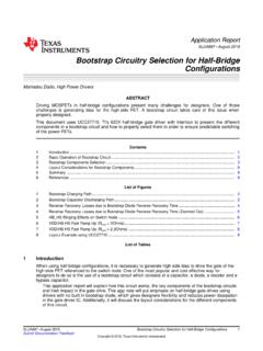
9 CAPACITANCE SERIES 100, CASE BCAPACITANCE (pF) ( pF to 51 pF) MHz500 MHz150 MHz(Typical)100 ESR (Ohms) MHz500 MHz150 MHz(Typical)100 CAPACITANCE (pF) (56 pF to 1000 pF)ESR VS. CAPACITANCE SERIES 100, CASE BQ100000100001000100101101000 MHz500 MHz150 MHz(Typical)100 CAPACITANCE (pF) ( pF to 51 pF)Q VS. CAPACITANCE SERIES 100, CASE B10000100101101000 MHz500 MHz150 MHz(Typical)100 CAPACITANCE (pF) (56 pF to 1000 pF)Q VS. CAPACITANCE SERIES 100, CASE B041222 rf microwave products The Important Information/Disclaimer is incorporated in the catalog where these specifications came from or available online at by reference and should be reviewed in full before placing any DATARF/Microwave Capacitors100B Series Porcelain Superchip Multilayer CapacitorsRF/Microwave Multilayer Capacitors (MLC)SERIES RESONANCE VS. CAPACITANCE SERIES 100, CASE BCURRENT RATING VS. CAPACITANCE SERIES 100, CASE BCAPACITANCE CHANGE VS. TEMPERATURE SERIES 100, CASE BCURRENT RATING VS.
10 CAPACITANCE SERIES 100, CASE BCAPACITANCE (pF)CAPACITANCE (pF)( pF to 51 pF)TEMPERATURE ( C)CAPACITANCE (pF)(56 pF to 1000 pF)FREQUENCY (GHz)RMS CURRENT (Amps)FREQUENCY (GHz)FREQUENCY (GHz) MHz500 MHz150 MHz(Typical)100010001001000-155254565851 05125145165(Typical)TC = +90 20 PPM/ C (-55 C to +125 C)TC = +90 30 PPM/ C (+125 C to +175 C)The current rating is based on a 65 C mounting surface and a device thermal resistance ( ) of 20 C/W. A power dissipation of 3W will result in a case temperature of 125 CThe current rating is based on a 65 C mounting surface and a device thermal resistance ( ) of 20 C/W. A power dissipation of 3W will result in a case temperature of 125 CDotted Line = Power dissipation limitedSolid Line = Voltage limited (Vrms)Dotted Line = Power dissipation limitedSolid Line = Voltage limited (Vrms)1000 MHz500 MHz150 MHz30 MHz150 MHz500 MHz1000 MHz30 MHz020321 rf microwave products The Important Information/Disclaimer is incorporated in the catalog where these specifications came from or available online at by reference and should be reviewed in full before placing any DATARF/Microwave Capacitors100B Series Porcelain Superchip Multilayer CapacitorsRF/Microwave Multilayer Capacitors (MLC)CURRENT RATING VS.