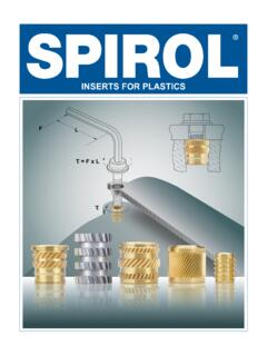
INSERTS FOR PLASTICS
the installation torque requirements to achieve a good threaded joint, and the pull-out values that meet the application load requirements. Helical knurls are the designer’s choice to maximize the torque resistance for a given diameter. The volume of these knurls must be such that sufficient
Download INSERTS FOR PLASTICS

Information
Domain:
Source:
Link to this page:
Documents from same domain
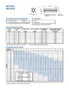
ISO 8752 EN 28752 - SPIROL International …
www.spirol.comD1 D2 D3 Pins with diameter ≥10mm may be supplied with a single chamfer configuration. B is less than nominal diameter LENGTH D C S B METRIC SPECIFICATIONS ISO 8752 EN 28752 ...

SPIROL Compression Limiters Design guide
www.spirol.com2 It is imperative that the proper Compression Limiter be designed into each application based on the specific requirements for that assembly, and that the plastic host be designed appropriately to ensure that bolted

ASME B18.8.2 LENGTH D C - SPIROL International …
www.spirol.comTitle: ASME B18.8.2 Slotted Pins Author: SPIROL Subject: SPIROL Slotted Spring Pins offerings to ASME B18.8.2 specifications. Keywords: slotted spring pins; B18.8.2 ...

Press-In Series 50 and 51 Inserts - SPIROL
www.spirol.comTitle: Press-In Series 50 and 51 Inserts Author: SPIROL Subject: Dimensional data for SPIROL's Press-In Inserts for Plastics Keywords: SPIRIOL, press in, brass inserts, specifications, dimensional data

Geschlitzte Spannhülsen - spirol.com
www.spirol.com2 D1 D2 D3 Spannhülsen mit Durchmesser ≥ 10mm können mit einer Anfasung geliefert werden. B ist kleiner als der Nenndurchmesser LÄNGE D C S B ISO 8752 EN 28752 STANDARDLÄNGEN IN MM

INSERTS FOR PLASTICS - SPIROL International Corporation
www.spirol.comINSERTS FOR PLASTICS. Cover2 Plastic Insert Bolt Friction Force Force L Torque ... The objective is to design an Insert with sufficient torque resistance to accommodate the tightening torque necessary to achieve sufficient axial tension load on the threaded joint to keep it together and prevent loosening,

Disc Springs - SPIROL
www.spirol.comOther factors such as the required life, the working temperature, and environmental conditions that may require corrosion protection or cleanliness requirements all will contribute to actual fatigue life and need to be taken into account. Design to Minimize Stresses: The fatigue life of a Disc Spring is directly related to the magnitude of stresses

Slotted Spring Pins Design Guide - SPIROL
www.spirol.comSTANDARD SIZES Nominal Pin Length Length Tolerance Length Tolerance - ISO 8752 4mm to 10mm ± 0.25mm 12mm to 50mm ± 0.50mm 55mm to 100mm ± 0.75mm Length Tolerance - DIN 1481 (Ref) 4mm to 10mm + 0.5mm 12mm to 50mm + 1.0mm 55mm to 100mm + 1.5mm METRIC SPECIFICATIONS Only available in high carbon (B) and austenitic stainless steel (D)

SPIROL Compression Limiters Design guide
www.spirol.comThe recommended torque values to produce this clamping load are provided on page 4. Determination of Compression Limiter Length Proper length specifications of both the Compression Limiter and the plastic component are crucial to the proper performance of the bolted joint. The recommended

INSERTS FOR PLASTICS - SPIROL
www.spirol.comStraight knurls, as opposed to diamond knurls, are the preferred design. Coarser knurls increase resistance to torque but they also induce greater stress on the plastic. In addition, the circumference of the Insert determines the knurl pitch so there are practical limitations on knurl design. Helical knurls, in comparison to straight knurls, lower
Related documents

Genius Current-source Analog I/O Blocks datasheet, GFK-0422D
www.cimtecautomation.comare suggested. Removing an Electronics Assembly _____ The block’s Electronics Assembly can be replaced with a compatible model without removing field wiring or reconfiguring the block. Terminal Assembly Retaining Screws (Qty. 2) Electronics Assembly Connector Pins 1. Unscrew the retaining screws at the top and bottom of the block. 2.
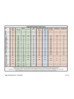
Suggested Assembly Torque Values - CopperState
www.copperstate.comSuggested Assembly Torque Values The tapped hole or nut must have an equal or greater proof load than the stud's minimum ultimate tensile strength. K= friction coefficient. PTFE coatings, lubrication, and assembly factors can alter these values. Values in this chart are advisory only, all applications vary. F1554 does not specify tightening ...

Torque Settings - Grampian Fasteners
www.grampianfasteners.comTorque Settings Suggested Starting Values The below estimated torque calculations are only offered as a guide. Use of its content by anyone is the sole responsibility of that person and they assume all risk. The importance of correct bolt tightening cannot be over emphasized. Determining the correct torque can however present problems.

FASTENER TORQUE CHARTS - Imperial Supplies
www.imperialsupplies.comTorque Values Suggested Assembly. Torque Values. When using anti-seize, reduce the lubed chart reading by 20% to properly torque. Always lubricate and use lubed torque values. Strength . Applicable . Grade. Sizes. Proof . Load . Stress (psi) Yield Strength . Min. Stress (psi) Tensile . Stress . Min. (psi) SAE Gr. 5. 1/4 to 1" dia. 1" dia. to 1 ...
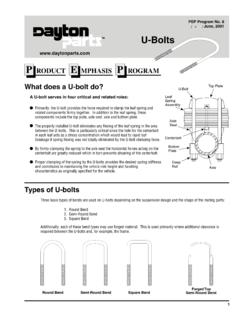
TM U-Bolts
www.suspensionspecialists.comTighten in the sequence shown to approximately 1/3 of recommended torque. Repeat, using the same sequence, gradually increasing the torque through a second and third stage until the recommended final torque is attained. Suggested Torque Values for U-bolts Torque U-bolts Evenly Dayton's Full Line of U-Bolt Kit Features Size (Diameter x Thread ...

Correct procedure for flange bolting Installation Procedure
www.ultratorq.comPass 2 – Using a torque wrench, torque to a maximum of 30% of the full torque first time around, according to the cross bolt tightening pattern. Pass 3 – Torque to a maximum of 60% of the full torque, according to the cross bolt tightening pattern. Pass 4 – Torque to the full torque, according to the cross bolt tightening pattern.