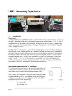
LAB 2: Measuring Capacitance
P443 L2 1 LAB 2: Measuring Capacitance 1. Introduction Capacitance A voltage difference V applied between two conductors will induce opposite charges +Q and –Q on each. Capacitance is the ratio of the induced charge to the applied voltage, C=Q/V, and is determined only by the shape of the conductors and the spacing between them.
Download LAB 2: Measuring Capacitance

Information
Domain:
Source:
Link to this page:
Documents from same domain

GEL 120 - PHYSICAL GEOLOGY LABORATORY
d32ogoqmya1dw8.cloudfront.netgel 120 – physical geology laboratory fall semester 2011 natural sciences/health & pe department mathematics and sciences division ... your laboratory manual to class.

GEOL 1301 – NATURAL HAZARDS AND DISASTERS
d32ogoqmya1dw8.cloudfront.netGEOL 1305 Syllabus – Fall 2009 – Page 3 Late assignments placed in the instructorʼs mailbox in the campus administration area MUST have the date of receipt stamped on them by the administrative assistant in the mailroom.

Graphing Sunspot Numbers
d32ogoqmya1dw8.cloudfront.net6. Estimate the dominant period of the sunspot signal. Explain and show your calculations below. 7. During the next 15 years about when do you expect the solar activity to be high
Berquist Thomas Nelson Community College
d32ogoqmya1dw8.cloudfront.netPete Berquist Thomas Nelson Community College Most students enrolled in my geology courses may never take a science class ever again, yet I find it likely …

Earth Science Introduction
d32ogoqmya1dw8.cloudfront.netGLOBE® 2003 Introduction - 6 Earth System Science Components of the Earth System The GLOBE program has students take measure-ments of many parts of the Earth’s systems. The table below indicates where the GLOBE investiga-tions lie with the components of the Earth system.

INTRODUCTION TO EARTH SCIENCE
d32ogoqmya1dw8.cloudfront.netObjectives: Introduction to Earth Science will expose you, the student, to the principles that underlie our understanding of how and why the Earth evolves. You …
COURSE INFORMATION Fall 2016 GEOL 1030-1 INTRO TO …
d32ogoqmya1dw8.cloudfront.netGEOL 1030-1 INTRO TO EARTH SCIENCE-LECTURE --- BASIC INFO --- LECTURE TIMES AND LOCATION: MWF 9:10a-10:05a in 452 KOM. ... If you miss a lecture, obtain notes and/or handouts from a student who was there. Absences for university sponsored events (e.g., athletics and

Syllabus for Earth Science
d32ogoqmya1dw8.cloudfront.net4 credits (3 lecture hours, 2 lab hours) Instructor: Joy Branlund ... You will be able to use YOUR notes (but no book, photocopied, borrowed or shared notes) for the Prep Checks. Homework (some completed in-class) ... Syllabus for Earth Science ...

September 2016 Newsletter Volume 2 Number 1
d32ogoqmya1dw8.cloudfront.net1 September 2016 Newsletter Volume 2 Number 1 TED’s President olumn By Jeff Thomas Dear TED Members: Let me start by welcoming all new and returning TED members, and I …

Overview of the Research Methods Used by Geoscience ...
d32ogoqmya1dw8.cloudfront.netSolutions • Establish and communicate norms for geoscience education research • GSA session to share methods and techniques Purpose • Provide overview of education research and framework to
Related documents
Series and Parallel Resonance - Rutgers University
www.ece.rutgers.eduDec 16, 2005 · characteristics of two resonant circuits on either side of resonance Overview In this experiment, the general topic of frequency response is introduced by studying the frequency-selectivity characteristics of two specific circuit structures. The first is referred to as the series-resonant circuit and the second as the parallel-resonant circuit.

BASIC ELECTRONIC EXPERIMENTS
pushkin.faculty.unlv.eduExperiment #3: Resistors in Series 13 Experiment #4: Parallel Pipes 14 Experiment #5: Comparison of Parallel Currents 15 Experiment #6: Combined Circuit 16 Experiment #7: Water Detector 17 Introduction to Capacitors 18 Experiment #8: Slow Light Bulb 20 Experiment #9: Small Dominates Large 21 Experiment #10: Large Dominates Small 22
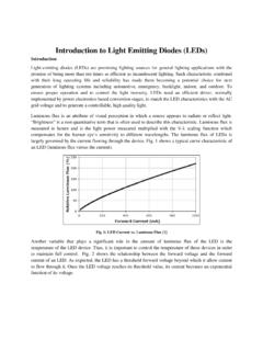
Introduction to Light Emitting Diodes (LEDs)
engineering.purdue.edustring of 6 series-connected LEDs in Experiment 8, as shown in the circuit diagram of Fig. 7. Fig. 7: The SEPIC converters to drive series-connected strings of LEDs [1] The input to the SEPIC converter ranges between 12-36V which is then stepped up/down to the desired output voltage level by appropriately changing the duty cycle.
PHYSICS (861)
cisce.orgcombination for identical cells in series, parallel andmixed groupingtorque experienced by a cu. Parallel combination of two cells of unequal emf. Series combination of n cells of unequal emf. (d) Statement and explanationof Kirchhoff's laws (ii) Magnetism andwith simple examples. The first is a conservation law for charge and the 2
![Class - XII Multiple Choice Question Bank [MCQ ] Term](/cache/preview/4/3/0/0/b/2/b/5/thumb-4300b2b57aa6bc47be8b515b63a28222.jpg)
Class - XII Multiple Choice Question Bank [MCQ ] Term
roraipur.kvs.gov.inand capacitance, combination of capacitors in series and in parallel, capacitance of a parallel plate capacitor with and without dielectric medium between the plates, energy stored in a capacitor. Chapter-1 Electric charges and fields Uniformly charged thin spherical shell (field inside and outside). Unit II: Current Electricity 15 Periods
DIGITAL ELECTRONICS: LOGIC AND CLOCKS
physicscourses.colorado.edu8.12, 8.16 are most relevant. Also have a look at section 5.14 on the 555 timer chip. LAB PREP ACTIVITIES Answer the following questions using Mathematica or do them by hand in your lab book. Question 1 Basic Digital Logic a. Read the lab thoroughly and enter in your lab book the circuit diagrams and truth tables of all the circuits you will test.
Frequency Response of Filters - Rutgers University
www.ece.rutgers.eduDec 16, 2005 · Experiment 2 Frequency Response of Filters 1 Introduction ... series with a high pass can either completely block all signals or give a band reject. By the same token, a low pass in parallel with a high pass can give either a bandpass or an all pass. These ideal characteristics will at best be approximated by real circuits. How closely this