MATLAB Basic Functions Reference - MathWorks
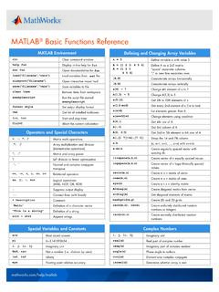
While-Loop % loops as long as a condition remains true n = 1; nFactorial = 1; while nFactorial < 1e100 n = n + 1; nFactorial = nFactorial * n; end % control structures terminate with end Further programming/control commands break Terminate execution of for- or while-loop continue Pass control to the next iteration of a loop
Download MATLAB Basic Functions Reference - MathWorks

Information
Domain:
Source:
Link to this page:
Documents from same domain
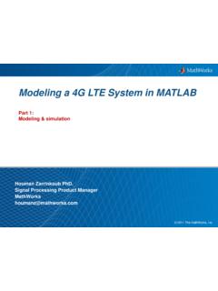
Modeling a 4G LTE System in MATLAB - MathWorks
www.mathworks.com4 Motivation – Very high capacity & throughput – Support for video streaming, web browsing, VoIP, mobile apps A true global standard – Contributions from all across globe

Generating LTE Waveforms - MathWorks
www.mathworks.comWhen we select an RMC, all the parameters are set up as defined in 3GPP TS 36.101 [1] Annex A.3. For R.13, the number of resource blocks is set to 50, the number of antennas to 4, and so forth.
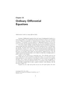
Chapter 15 Ordinary Differential Equations - mathworks.com
www.mathworks.coma second order method with a third order method to estimate the step size, while ode45 compares a fourth order method with a fifth order method. The letter “s” in the name of some of the ode functions indicates a stiff solver.

Using Model-Based Calibration Toolbox Multimodels for ...
www.mathworks.comUsing Model-Based Calibration Toolbox Multimodels for Cycle-Optimized Diesel Calibration Joshua P. Styron Ford Motor Company ABSTRACT Modern diesel engines have many degrees of freedom that must be simultaneously adjusted to optimize efficiency,

Control System Design and Rapid Prototyping Using Simulink
www.mathworks.com11 System Identification Integrated into PID Tuner in Simulink Control Design Compute plant transfer function from simulation input-output data when exact

MIL/SIL/PIL Approach A new paradigm in Model Based …
www.mathworks.comBitte decken Sie die schraffierte Fläche mit einem Bild ab. Please cover the shaded area with a picture. (24,4 x 11,0 cm) MIL/SIL/PIL Approach A new paradigm in Model Based Development

Developing Battery Management Systems with Simulink and ...
www.mathworks.comWHITE PAPER | 5 Figure 2. Equivalent circuit of a battery with three distinct time constants, internal resistance, and open circuit potential. By incorporating Simscape Electrical™ components, you can scale up from the unit cell level to the module and pack level and intuitively combine cells with surrounding circuitry.
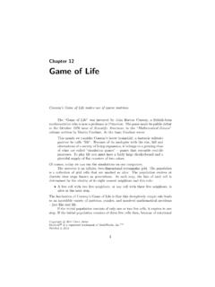
Chapter 12 Game of Life - MathWorks
www.mathworks.comalternations of a society of living organisms, it belongs to a growing class of what are called “simulation games” – games that resemble real-life processes. To play life you must have a fairly large checkerboard and a plentiful supply of flat counters of two colors. Of course, today we can run the simulations on our computers.

R2020b Updates Release Notes - MathWorks
www.mathworks.comTo learn more about Updates, see Updates: Frequently Asked Questions. Important Limitations • MATLAB Parallel Server, MATLAB Parallel Server for Amazon EC2, and MATLAB Parallel Server - Private Cloud: Install the Update on all client and worker installations.

Chapter 10 Eigenvalues and Singular Values
www.mathworks.comConsequently, the three eigenvalues are λ1 = 1, λ2 = 2, and λ3 = 3, and Λ = 1 0 0 0 2 0 0 0 3 . The matrix of eigenvectors can be normalized so that its elements are all integers: X = 1 −4 7 −3 9 −49 0 1 9 . It turns out that the inverse of X also has integer entries: X−1 = 130 43 133 27 9 …
Related documents

All aboard! Detailed fare in orf ma tion First bus / last ...
www.transitchicago.com$20 $25 $75 Full $2.50 $2.25 Bus $2.50* ‘L T’ rain $5 $55 $5 Reduced $1.10 ... • AM rush: Clockwise loop in Hyde Park, enters Lake Shore Drive NB at 47th; exits SB at 57th. ... Detailed fare in orf ma tion-CTA PACE. X: PURPLE: YELLOW: Base/regular fares Pay-per-ride fares, as deducted from value in a Ventra Transit Account ...

Electronic Control Systems IQAN System Products
www.parker.comCurrent loop inputs for 4-20 mA, Timer inputs (used for frequency, PWM and pulse devices) and Digital (on-off) inputs. Voltage and Timer inputs share pin positions with Digital inputs. The IQAN-MC41 has 2 double proportional outputs for controlling valves. These outputs can control up to 2 bi-directional proportional valve sections or 2 single
Graph Theory Lecture Notes
www.personal.psu.edu1.3 A self-loop is an edge in a graph Gthat contains exactly one vertex. That is, an edge that is a one element subset of the vertex set. Self-loops are illustrated by loops at the vertex in question.4 1.4 Representing each island as a dot and each bridge as a line or curve connecting

Manual Rosemount 2051 Selectable HART 4.20 mA HART ...
www.emerson.comsignal on the 4–20 mA output. An optional LCD display can be ordered that connects directly to the interface board which maintains direct access to the signal terminals. The display indicates output and abbreviated diagnostic messages. A glass display cover is provided. For 4-20 mA HART output, the LCD display features a two-line display.
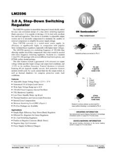
LM2596 - 3.0 A, Step-Down Switching Regulator
www.onsemi.com20 mA Quiescent Current (Note 5) IQ 5.0 10 mA Standby Quiescent Current (ON/OFF Pin = 5.0 V (“OFF”)) (Note 6) Istby 80 200 250 A ON/OFF PIN LOGIC INPUT Threshold Voltage 1.6 V Vout = 0 V (Regulator OFF) VIH 2.2 2.4 V Vout = Nominal Output Voltage (Regulator ON) VIL 1.0 0.8 V ON/OFF Pin Input Current ON/OFF Pin = 5.0 V (Regulator OFF) IIH ...

SCIENCE (52) - CISCE
cisce.orgpractical work carrying 20 marks. The paper will be divided into . two . sections, Section I (40 marks) and Section II (40 marks). Section I (compulsory) will contain short answer questions on the entire syllabus. Section II . will contain six questions. Candidates will be required to answer any . four . of these . six . questions. Note:

Voltage Transducer LV 25-P I = 10 mA P N For the ...
www.lem.comClosed loop (compensated) voltage transducer using the Hall effect ... 8July2021/version 20 LEM reserves the right to carry out modifications on its transducers, in order to improve them, without prior notice LEM nternational A Chemin des Aul 8 ... mA 0 to 10 Supply voltage U C V DC ...
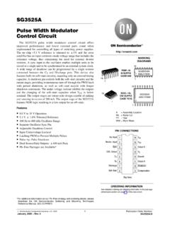
SG3525A - Pulse Width Modulator Control Circuit
www.onsemi.comLine Regulation (+8.0 V ≤ VCC ≤ +35 V) Regline − 10 20 mV Load Regulation (0 mA ≤ IL ≤ 20 mA) Regload − 20 50 mV Temperature Stability Vref/ T − 20 − mV Total Output Variation Includes Line and Load Regulation over Temperature Vref 4.95 − 5.25 Vdc Short Circuit Current (Vref = 0 V, TJ = +25°C) ISC − 80 100 mA

source transformations - Iowa State University
tuttle.merc.iastate.edu20 V 7.5 kΩ 2 mA Transform the voltage source / ... 1 kΩ 15 mA 40 V 1 kΩ 1 kΩ 15 V Writing a KVL loop equation and solving for i R1 gives L5 = 96 967 5 + 5 = 9 9 N |+ N | This is the correct answer. = . P$ EE 201 source transformations – 8