Transcription of Generating LTE Waveforms - MathWorks
1 Generating LTE Waveforms Quickly generate LTE Waveforms with a few clicks or three lines of MATLAB code Validate radio frequency (RF) design or wireless system with LTE-compliant signals Generating LTE Waveforms can require a deep level of understanding of the LTE standard, as well as many years of effort. LTE System Toolbox lets you generate Waveforms easily. You can then use these Waveforms for many purposes including validating an RF component on a realistic LTE waveform , assessing the impact of an LTE interferer on another wireless system (or the opposite), or testing the correctness of your LTE receiver on a f lexible, synthesized LTE waveform . LTE System Toolbox offers complete control of LTE waveform generation including standard-compliant reference measurement channels (RMCs) and fixed reference channels (FRCs), uplink and downlink [1] Annex and [2] Annex A, and downlink E-TM test models [3] Section example shows how to generate LTE Waveforms such as RMCs for uplink and downlink, as well as test model Waveforms (E-TM) interactively or with simple MATLAB code.
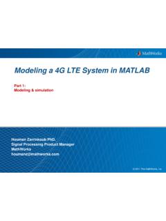
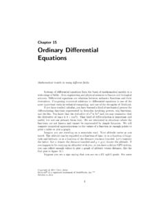
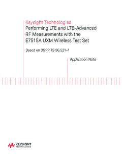
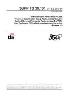
2 We also visualize characteristics of the generated signals in the time and frequency domain. Generating Downlink RMC3 GPP defines many standard-compliant reference signals (RMC, FRC and E-TM). Refer to TS , Annex A [1] for more detail on on the LTE Downlink RMC Generator Application Tool, or typing the function lteRMCDLTool at the MATLAB prompt, launches a parameter-driven tool for generation of the RMC Waveforms . We can select one of the supported RMCs, such as in Figure 1, and further configure some of the parameters. Figure 1. Select one of the supported RMCs from the LTE Downlink RMC GeneratorWhen we select an RMC, all the parameters are set up as defined in 3 GPP TS [1] Annex For , the number of resource blocks is set to 50, the number of antennas to 4, and so forth. We can then generate the standard-compliant waveform simply by clicking Generate 10 Subframes of RMC WaveformFigure 2 shows the real part of subframes 0 through 9 of the I/Q waveform .
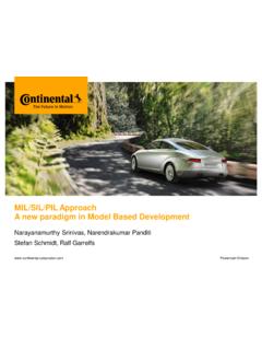
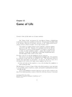
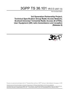
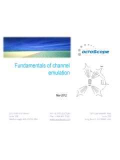
3 A few characteristics are easy to recognize: There are four plots, each corresponding to one of the four transmit antennas for The sixth subframe (subframe 5) includes a hole, consistent with Table [1], which specifies that the sixth subframe should not contain any data physical downlink shared channel (PDSCH) transmission. In the sixth subframe, the dark blue plot includes more data because the primary and secondary synchronization signals (PSS/SSS) are located in that subframe and transmitted from only one antenna. Figure 2. Real part of subframes 0 through 9 of the I/Q 3 shows that the 50 resource blocks allocated for correspond to a 10 MHz signal 3. Fifty resource blocks allocated for correspond to a 10 MHz signal bandwidth. In Figure 4 we see the absolute value of the grid for antenna port 0. A few distinctive features are that: No data is allocated in subframe 5 (the sixth subframe) as shown by the low energy. Primary and secondary synchronization sequences (PSS/SSS) stand out in the middle of the frequency range in subframes 0 and 5.
4 The PDSCH allocation in all subframes but subframe 5 encompasses the whole bandwidth. Figure 4. Absolute value of grid for antenna port 0. Generating Downlink RMC from MATLAB PromptThe following three lines of MATLAB code generate exactly the same signal directly without using the application. This provides an efficient way to further tailor the waveform , as well as automate the generation of a large number of such Generate the configuration for = lteRMCDL( );% Generate a random signal to transmitData = randi([0 1], 1, sum( ));% Generate the standard-compliant data[ waveform , txgrid, RMCcfgOut] = lteRMCDLTool(rmc, Data); Generating Uplink FRCsLTE System Toolbox supports generation of uplink reference signals in much the same way as RMCs, using the lteRMCULTool application and E-UTRA Test Model (E-TM) WaveformRMCs and FRCs are useful signals for investigating the throughput of an LTE system [1] section 8 and [2] section 8. These Waveforms include a single user that typically occupies the whole , testing transmitter performance requires more dynamic signals, such as E-TMs [3] section 6.
5 In those channels, the resource allocation for a user (PDSCH) changes with every subframe, and there can be several users (PDSCHs) transmitting at the same System Toolbox lets us easily generate E-TM models with lteTestModelTool. Similarly to RMC and FRC waveform generation above, an interactive application (see Figure 5) and a function are available, offering the choice between a few mouse clicks and very few lines of MATLAB code. Figure 5. The lteTestModelTool interactive application. 2014 The MathWorks , Inc. MATLAB and Simulink are registered trademarks of The MathWorks , Inc. See for a list of additional trademarks. Other product or brand names may be trademarks or registered trademarks of their respective 09/14 SummaryLTE System Toolbox provides a comprehensive set of applications and functions for easy access to standard-compliant generated from the interactive application or the equivalent command line MATLAB code, those Waveforms enable thorough testing of LTE components and systems on realistic LTE signals.
6 One of the key benefits, in addition to the out-of-the-box compliance, is that no LTE expertise is required to generate such Waveforms . This means that non-LTE experts now have the ability to validate the suitability of their design for LTE without the need for a costly time investment in the details of the LTE standard. References[1] 3 GPP TS User Equipment (UE) Radio Transmission and Reception[2] 3 GPP TS Base station (BS) Radio Transmission and Reception[3] 3 GPP TS Base station (BS) Conformance TestingProducts UsedMATLABLTE System ToolboxLearn MoreIntroducing LTE System Toolbox 44:57 (Webinar) Downlink Test Model (E-TM) waveform Generation (Example) Generation and Analysis using LTE System Toolbox with Test and Measurement Equipment (Example) Error Vector Magnitude (EVM) Measurement (Example) Uplink EVM and In-Band Emissions Measurements (Example)