Power Circuits and Transformers - Lab-Volt
Ex. 1-3 Power in DC Circuits ..... 23 Distinctions between energy, work and power. Determining power in dc circuits, power formula. Ex. 1-4 Series and Parallel Circuits ..... 33 Solving circuits using Kirchhoff's voltage and current laws. Using circuit measurements to confirm
Download Power Circuits and Transformers - Lab-Volt

Information
Domain:
Source:
Link to this page:
Documents from same domain
AC/DC Motors and Generators - Lab-Volt
lvsim.labvolt.comtransfer to and storage and processing in electronic systems, no matter whether in whole or in part, shall ... Series, Shunt, and Compound DC Motors ... LVSIM®-EMS recreates a three-dimensional classroom laboratory on a computer ® ® AC/DC Motors and Generators. AC/DC Motors and Generators ...
Conventional DC Machines and Universal Motor - …
lvsim.labvolt.comtraining documentation for the training of his/her staff at the purchaser's site/location with ... Ex. 2-2 Separately-Excited, Series, Shunt, and Compound Motors .... 63 DISCUSSION ... This course, Conventional DC Machines and Universal Motor, ...
Single-Phase Induction Motors - LVSIM-EMS
lvsim.labvolt.comThe present manual, Single-Phase Induction Motors, introduces the student to the operation and characteristics of the following two types of single-phase induction motor: capacitor-start induction motor and split-phase induction motor.
AC/DC Motors and Generators
lvsim.labvolt.comThe operating principles of direct current (DC) motors and generators. The different types of dc motors and generators ... capacitive loads. Ex. 6-3 Frequency and Voltage Regulation ..... 257 Effect of resistive, inductive, and capacitive loads on ... as well as programmable meter functions, thereby ...

Three-Phase AC Power Circuits
lvsim.labvolt.comElectricity and New Energy Three-Phase AC Power Circuits Student Manual 86360-00

LVSIM-EMS Help Table of Contents - Lab-Volt
lvsim.labvolt.comPermanent Magnet DC Motor (86357) Single-Phase AC Power Circuits (86358) Three-Phase AC Power Circuits (86360) Three-Phase Rotating Machines (86364) Single-Phase Power Transformers (86377) Three-Phase Transformer Banks (86379) Conventional DC Machines and Universal Motor (88943)
Related documents
CIRCUITS LABORATORY EXPERIMENT 9 Operational Amplifiers
classes.engineering.wustl.eduCIRCUITS LABORATORY EXPERIMENT 9 Operational Amplifiers 9.1 INTRODUCTION An operational amplifier ("op amp") is a direct-coupled, differential-input, high- gain voltage amplifier, usually packaged in the form of a small integrated circuit.
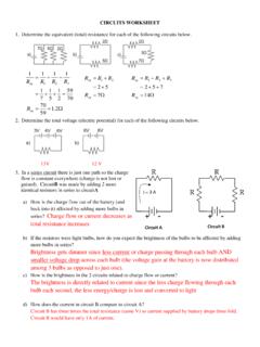
Circuit A Circuit B - Livingston Public Schools
www.livingston.orgCIRCUITS WORKSHEET 1. Determine the equivalent (total) resistance for each of the following circuits below. : 2. Determine the total voltage (electric potential) for each of the following circuits below. 13V 12 V 3. In a series circuit there is just one path so the charge flow is constant everywhere (charge is not lost or gained).
Snubber Circuits Suppress Voltage Transient Spikes in ...
pdfserv.maximintegrated.comsuppression circuits (voltage snubbers) that can be used to suppress these transients on both the primary and secondary side. The flyback topology ( Figure 1A ) results in significant cost and space savings for multiple output power

14: Power in AC Circuits - Imperial College London
www.ee.ic.ac.ukCosine Wave RMS 14: Power in AC Circuits •Average Power •Cosine Wave RMS •Power Factor + •Complex Power •Power in R, L, C •Tellegen’s Theorem •Power Factor Correction •Ideal Transformer •Transformer Applications •Summary E1.1 Analysis of Circuits (2017-10213) AC Power: 14 – 3 / 11 Cosine Wave: v(t) = 5cosωt.Amplitude is V = 5V. Squared Voltage: v2(t) …
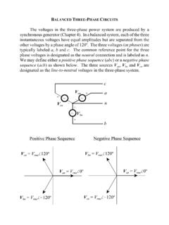
BALANCED THREE-PHASE CIRCUITS - Mississippi State …
my.ece.msstate.eduThe concepts of power factor and the complex power triangle can also be extended to a balanced three phase power system without loss of generality. The three-phase power factor is defined by the same single-phase equation since the relative angle between the voltage and current is equal in all three phases of a balanced three-phase system.
Drive circuits for Power MOSFETs and IGBTs
www.st.comPower MOSFETs and IGBTs can easily be slowed by adjusting the value of the gate resistor. This feature can be used as an EMI reducer in applications where the mains phase angle is switched (figure 13), for example light dimmer circuits. Conventional dimming circuits are controlled by TRIACs. Turning a TRIAC on or off generates voltage
Design of Snubbers for Power Circuits
www.cde.comthese circuits, and in fact most power electronics circuits, have within them the same switch-diode-inductor network shown within the dotted lines. The behavior of this network is the same in all these circuits which means that we only have to solve the snubber design problem for one circuit to apply it to all of the others.
Chapter 21: RLC Circuits - Department of Physics
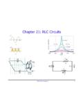
www.phys.ufl.eduPHY2054: Chapter 21 19 Power in AC Circuits ÎPower formula ÎRewrite using Îcosφis the “power factor” To maximize power delivered to circuit ⇒make φclose to zero Max power delivered to load happens at resonance E.g., too much inductive reactance (X L) can be cancelled by increasing X C (e.g., circuits with large motors) 2 P ave rms=IR rms ave rms rms rms cos

Circuits - Department of Physics
www.phys.ufl.eduCircuits ÎThe light bulbs in the circuits below are identical. Which configuration produces more light? (a) circuit I (b) circuit II (c) both the same Circuit II has ½ current of each branch of circuit I, so each bulb is ¼ as bright. The total power in circuit I is thus 4x that of circuit II.