
Practice Problems for FE Fluid Mechanics
Example 30 Inthepipesystemdepictedbelow,thedischargeinpipeABis100 m3/sec. Branch 1 is 500 m long, and it has a diameter of 2 m and a friction factor of 0.018. Branch 2 has a length of 400 m, diameter of 3 m, and a friction factor of 0.02.
Download Practice Problems for FE Fluid Mechanics

Information
Domain:
Source:
Link to this page:
Documents from same domain

Chapter 2. Atomic Structure and Interatomic Bonding
web.eng.fiu.eduChapter 2. Atomic Structure and Interatomic Bonding Interatomic Bonding –Bonding forces and energies –Primary interatomic bonds –Secondary bonding –Molecules Bonding Forces and Energies • Considering the interaction between two isolated atoms as they are brought into close proximity from an infinite separation. • At larger distances ...
Chapter 4 : ERP Implementation Methodologies and Strategies
web.eng.fiu.eduimplementation, and are kept at the forefront of the strategy. It is crucial that management executives and project stakehold-ers establish expectations for the project. Their role is to ensure ... • Budget • Funding CHAPTER 4 Dunaway – ERP …

Mechanical Vibrations FUNDAMENTALS OF VIBRATION
web.eng.fiu.edu• Joseph Sauveur (1653–1716) coined the word “acoustics” for the science of sound. • Sir Isaac Newton (1642–1727) his law of motion is routinely used to derive the equations of motion of a vibrating body. • Brook Taylor (1685–1731), obtained the natural frequency of vibration observed by Galilei and Mersenne.

Chapter 9: Phase Diagrams
web.eng.fiu.eduPhase Diagrams • Indicate phases as function of T, Co, and P. • For this course:-binary systems: just 2 components.-independent variables: T and Co (P = 1 atm is almost always used). • Phase Diagram for Cu-Ni system Adapted from Fig. 9.3(a), Callister 7e. (Fig. 9.3(a) is adapted from Phase Diagrams of Binary Nickel Alloys , P. Nash

OVERVIEW OF HEURISTIC OPTIMIZATION
web.eng.fiu.eduOPTIMIZATION (Eberhart Kennedy -1995) A robust stochastic optimization technique inspired by the social behavior of swarms of insects or flocks of birds –maximize “food”. Apply the concept of social interaction to problem solving. Developed in 1995 by James Kennedy (social-psychologist) and Russell Eberhart (electrical engineer).

Chapter 16: Composite Materials
web.eng.fiu.edustrength of a ceramic • structure materials for aircraft engine: low densities, strong, stiff, abrasion and impact resistant and corrosion resistant. Chapter 16 - 2 ... Composite Hybrid Materials, The Macmillan Company, New York, 1981.] • Stacked and bonded fiber-reinforced sheets

Experiment One (1) Tensile Stress Testing
web.eng.fiu.eduor Pa). In Equation (3.3-2), å is the strain measured in in/in (m/m) in the direction of the applied load. Since strain is dimensionless, the elastic modulus is measured in units of psi (Pa). It is important to realize that Equations above is valid only for uniaxial tension and is a special case of a generalized set of relations known as Hooke ...

Milliequivalents, Millimoles, and Milliosmoles
web.eng.fiu.eduStep 2: Calculate equivalent weight Equiv weight = molecular weight KCl divided by valence Since valence of KCl = 1, Equiv weight = 74.5/ 1 Step 3: 1 mEq KCl = 1/1000 x 74.5 g = 0.0745 g = 74.5 mg Step 4: 4 mEq KCl = 74.5mg x 4 = 298 mg/ml OR using the equation listed before: mg/ml = mEq/ml * atomic, molecular or formula weight valence ...

Experiment Two (2) Torsional testing of Circular Shafts
web.eng.fiu.eduDetermination of Modulus of Rigidity, Shear Modulus G and Torsional Stress for Steel and Aluminum. A. Using the reading of above to calculate the shear modulus and torsional stress for Steel, Aluminum and Brass, by using the following formulas. Compare the experimental results with theoretical values. Θ = [180*T*L/(π*J*G)] (eq. 1) τ= T*C/J ...
Related documents
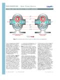
E N G I N E E R I N G - Gear Pump Basics - Liquiflo
www.liquiflo.compulseless flow, low NPSHR (net positive suction head required), high MTBM (mean time between maintenance), high-pressure and high-temperature capability, precise and accurate metering, and availability in multiple seal configurations or sealless mag-drives. Liquiflo has over 35 years experience in designing and manufacturing quality
Positive Displacement Pump Basics - Fristam
fristam.ca(psi) – Suction Pressure (psi) The pressure gradient inside the pump shows that the positive pressure on the suction side (Figure 10) of the pump assists the rotor movement and reduces the product slip inside the pump. Pressurized tanks and product levels above the pump on the suction side contribute to positive suction pressures.

SLURRY PUMPING MANUAL - pumpfundamentals.com
www.pumpfundamentals.comGauge head at pump suction, referred to pump centreline – positive if above atmospheric head and negative if below m fluid Hi Head loss at inlet to suction pipework also: Combined head loss in suction pipework m fluid Hm Total head required by a slurry pumping system also: Total head developed by a pump when handling slurry m slurry HR Head ...

Practical Considerations in Pump Suction Arrangements
www.pdhonline.comNet Positive Suction Head available (NPSHA), all spell serious trouble from vibration, cavitation, lowered capacity, and reduced efficiency. While the Engineer may not have large control over some of the inher-ent process factors, with planning and foresight many times the pump suction conditions can be optimized in the design stage.

Hydraulic Considerations in Pumping System Design
cdn.ymaws.comn • NPSH A = Atmos. Head + Static Suction Head –Suction HL • Standard atmospheric pressure = 14.7 psi (34 ft. head) •Net Positive Suction Head Required (NPSH R) • Furnished by pump manufacturer –pump specific • Increases with pump flow •NPSH A < NPSH R Cavitation • Typically occurs in systems with static lift • Could occur in flooded suction scenario with …

Fundamentals of Pumps - d6s74no67skb0.cloudfront.net
d6s74no67skb0.cloudfront.netthe relationship between net positive suction head available and net positive suction head required that is necessary to avoid cavitation. 1.5. LIST. three indications that a centrifugal pump may be cavitating. 1.6. LIST. five changes that can be made in a pump or its surrounding system that can reduce cavitation. 1.7.

Common Pump Formula - Home - M.G. Newell
www.mgnewell.com(Net Positive Suction Head available) NPSHa = Pa ± h s – h fs – Pvp (+h s for flooded section) (-h s for suction lift) where: Pa = pressure absolute above fluid level (bar) h s = static suction head (m) h fs = pressure drop in suction line (m) Pvp = vapor pressure (bar a) Or Pa = pressure absolute above fluid level (psi) h s = static ...

Pump Maintenance
www.mi-wea.org•net positive suction head - npsh •net positive discharge head - npdh •pressure gauges – actual npsh & npdh conditions •flow meter – gpm . basic care •performance parameters - centrifugal •replaceable wear components •packing •wear rings •impellers .

THE COMPONENTS OF TOTAL HEAD
www.pumpfundamentals.comThe Net Positive Suction Head Available (N.P.S.H.A.) is the total energy per unit weight, or head, at the suction flange of the pump less the vapor pressure head of the fluid. This is the accepted definition which is published by the Hydraulic Institute’s Standards books

Best practices in pump system design
www.xylem.comNet positive suction head required (NPSHr) is a pump characteristic that is not related to the system. All pump NPSHr’s are different and the values can be obtained from the pump manufacturer. Hole in pump impeller vane. Impeller damage. 4 By definition, because there is a large cross section at position