Transcription of Experiment Two (2) Torsional testing of Circular Shafts
1 Experiment Two (2). Torsional testing of Circular Shafts Introduction: Torsion occurs when any shaft is subjected to a torque. This is true whether the shaft is rotating (such as drive Shafts on engines, motors and turbines) or stationary (such as with a bolt or screw). The torque makes the shaft twist and one end rotates relative to the other inducing shear stress on any cross section. Failure might occur due to shear alone or because the shear is accompanied by stretching or bending. Objective: To determine Shear Modulus of Elasticity (G) of some steel , Aluminum and Brass Circular Shafts and develop a relationship among the Torque (T0 and Clamping length (L) and the angle of twist ( ).)
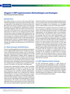
2 Apparatus: 1. Torsion testing Rig, Apparatus above. Dr. S. E. Beladi, PE Mechanics of Materials Lab Page |1. Experiment Two- Torsional test The device will apply a torque to the shaft fixed between two holding clamps. Torque is developed by applying a force of F via load handle above the system thru a distance spindle arm. 2. The shaft should be securely tightened between the end holding clamps as much as possible. 2. The measuring dial will measure the displacement of an arm handle at a fixed distance. 3. This displacement is proportionally related to the angle of twist of the rod.
3 Theory: As the two aforementioned names imply, the test specimen will encounter shearing stresses as a result of the twisting of the specimen and the specimen which is more rigid, or more resistant to twisting, will have a higher modulus of rigidity. Again, the modulus of rigidity is a material property and, under non-extreme environmental conditions, is a constant value for each material. In this Experiment two or three specimens will be tested. These specimens will possess identical geometric measurements and differ only in material type.
4 The various materials tested may include brass, aluminum and steel . The experimental determination of the modulus of rigidity is similar to the experimental determination of the modulus of elasticity. However, the modulus of elasticity was determined by the application of an axial load and the test specimen was not plastically deformed. The modulus of elasticity was calculated by determining the slope of the axial stress versus axial strain curve. The modulus of rigidity will be determined by twisting the test specimen and calculating the slope of the shear stress versus shear strain curve.
5 In addition, the torsion test specimen will be twisted to failure in order to determine the shear stress at the limit of proportionality. The shear stress at the limit of proportionality is the largest value of the shear stress for which the material will behave elastically. Throughout this discussion the plot of the shear stress versus shear strain has been mentioned. The actual values recorded experimentally, as the specimens are being twisted, are the angle of twist applied to the specimen and the corresponding value of torque at a particular angle of twist.
6 The instructor should indicate location of the 6 degree and 360 degree Vernier scale and the torque scale. Equations are provided within the student manual to convert the twist and torque values to the corresponding shear stress and shear strain values. Preparation for the lab: Simply answer the following questions: 1. Is there a relationship between the modulus of rigidity and the modulus of elasticity of a material? 2..2. What are the units of the modulus of rigidity? 3. Which material, brass or steel , would you expect to have a higher modulus of rigidity?
7 4. If testing steel and aluminum, which material would fail at a higher angle of twist? 5. Which specimen would have a greater value of torque at failure? Dr. S. E. Beladi, PE Mechanics of Materials Lab Page |2. Experiment Two- Torsional test Procedure and Experimental setup a. Circular Shafts 1. Mount the shaft onto test equipment holding chucks, by losing the tightening screws and slide in the rod. Tighten the rod by securing tightening screws and sliding arm . 2. Measure a fixed length, of 200 mm span length. Measure the diameter of the rod.
8 3. Measure the distance between load application point and the center of rod. Compare this measurement with specified value on the Lab poster. 4. Measure the distance between the Vernier measuring point and the center of the rod. Compare this value with equipment value. 5. Set the Vanier reading to Zero, or register the Zero Load location. 6. Apply Loads gradually and record the Deflection at Vernier point. Make sure that if the gauge reader has been rotated more than one full rotation, keep record of that. 7. Increase the load in fraction of 100 gm, force from Zero to 2000 gm, record the deflections.
9 8. Repeat for each specimen. 9. Change the length from 150 mm to maximum span, steep of 100 mm 450 mm and repeat the measurements. Dr. S. E. Beladi, PE Mechanics of Materials Lab Page |3. Experiment Two- Torsional test Use the following Suggested Table for gathering Data Torsion test Data Rod Distance Distance Test Date/. Specimen steel Diameter D1 mm D2 mm Time Material mm Angle of Modulus Applied Measured Twist Calculated of Length Load Deflection Radian Angle of Twist Rigidity Set Length 100. 200. 300. 400. 500. 600. 700. 800. 900.
10 1000. 1100. 1200. 1300. 1400. 1500. 1600. 1700. 1800. 1900. 2000. Determination of Modulus of Rigidity, Shear Modulus G and Torsional Stress for steel and Aluminum. A. Using the reading of above to calculate the shear modulus and Torsional stress for steel , Aluminum and Brass, by using the following formulas. Compare the experimental results with theoretical values. = [180*T*L/( *J*G)] (eq. 1). = T*C/J (eq. 2). J = * d4 /32 (eq. 3). Dr. S. E. Beladi, PE Mechanics of Materials Lab Page |4. Experiment Two- Torsional test Data: Theoretical values for Shear Modulus of elasticity (modulus of Rigidity): Aluminum G= 26 GPa, E= 70 GPa steel G= 80 GPa E= 270 GPa Brass ( red) G= 44 GPa E= 120 GPa Required Calculations: 1.