Precision Rectifier Circuits - Engineering
Precision Rectifier Circuits Rectifier circuits are used in the design of power supply circuits. In such applications, the voltage being rectified are usually much greater than the diode voltage drop, rendering the exact value of the diode drop unimportant to the proper operation of the rectifier. Other applications exists, however, where this ...
Download Precision Rectifier Circuits - Engineering

Information
Domain:
Source:
Link to this page:
Documents from same domain

The Transformer - University of Ottawa
www.site.uottawa.ca2 Transformer Core • The composition of a transformer core depends on voltage, current, and frequency. Commonly used core materials are air, soft iron, and steel.
Inference Rules and Proof Methods - University of …
www.site.uottawa.caIntro Rules of Inference Proof Methods Rules of Inference for Propositional Logic Which rule of inference is used in each argument below? Alice is a Math major.
Precision Rectifier Circuits - University of Ottawa
www.site.uottawa.caPrecision Rectifier Circuits ... rendering the exact value of the diode drop ... amplifier with the inverting precision half-wave rectifier to get the

ELG4126: Sustainable Power Systems - University of Ottawa
www.site.uottawa.caELG4126: Sustainable Power Systems Concepts and Applications: You should be familiar with Introduction (Structure of Power Systems) Basic Principles (AC Power) Generation Transmission Lines Transformers ... Transmission system Suspension insulators Lightning arrestors
Combinatorial Testing and Covering Arrays
www.site.uottawa.caCombinatorial Software Testing Covering Arrays Software and Network Testing We want to test a system: a program ... Introduction 6 Example 1.1.2. For our second example, we look at the circuit diagram in Figure 1.1. ... Combinatorial Testing and Covering Arrays Lucia Moura. Combinatorial Software Testing Covering Arrays

Wind Turbine Generators for Wind Power Plants
www.site.uottawa.ca• Usually wind turbines are classified by their mechanical power control, and further by their speed control. • All turbine blades convert the motion of air across the air foils

Lecture 11: Introduction to Network Management
www.site.uottawa.ca1 Prof. Shervin Shirmohammadi CEG 4185 11-1 Lecture 11: Introduction to Network Management Prof. Shervin Shirmohammadi SITE, University of Ottawa Prof. Shervin Shirmohammadi CEG 4185 11-2
Basics : the Requirements Engineering Process
www.site.uottawa.ca10 SEG3101 (Fall 2010). Basics – the RE process. Notes on previous slide • This looks like the waterfall process model, but this diagram describes a quite different situation. •The layers correspond to step-wise refinement in terms of component decomposition. •For instance, the transition from the first to the second layer is the typical RE process: one starts with the information from

Fundamentals of Alternating Current - Engineering
www.site.uottawa.caApply circuit analysis using phasors. ... Fundamentals of Alternating Current 3 Figure 12-1 Sinusoidal wave values. 12.2.1 Radian and Degree A degree is a unit of measurement in degree (its designation is ° or deg), a turn of a ray by the 1/360 part of the one complete revolution. ...
Chapter 3 Fourier Series Representation of Period Signals
www.site.uottawa.ca3.2 The Response of LTI Systems to Complex Exponentials It is advantageous in the study of LTI systems to represent signals as linear combinations of basic signals that possess the following two properties: • The set of basic signals can be used to construct a broad and useful class of signals.
Related documents

Three Phase Uncontrolled Rectifier
ceng.tu.edu.iquncontrolled bridge rectifier with two different types of loads namely the R – L – E type load and the capacitive load will be described. 12.3.1 Operation of a 3 phase full wave uncontrolled bridge rectifier supplying an R – L – E load This type of load may represent a dc motor or a battery. Usually for driving these loads a
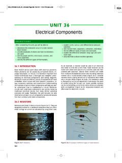
Electrical Components - Pearson
www.pearsonhighered.comElectrical circuits on different pieces of equipment will have similarities. Most circuits will have resistors, capacitors, re-lays, contactors, switches, and transformers. Understanding the function of each of these components will help you bet-ter understand how …
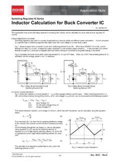
Inductor Calculation for Buck Converter IC - Rohm
fscdn.rohm.comcircuits. Buck (Step-Down) Converter Switching regulators are used in a variety of applications to provide stable and efficient power conversion. A buck converter is a specific type of switching regulator that steps down the input voltage to a lower level output. Fig. 1 shows a typical buck converter circuit when switching element Q1 is ON.

Thyristor Theory and Design Considerations
edisciplinas.usp.brwhich act as open circuits capable of withstanding the rated voltage until triggered. When they are triggered, thyristors become low−impedance current paths and remain in that condition until the current either stops or drops below a minimum value called the holding level. Once a thyristor has been triggered, the trigger current can
ELECTRONIC DEVICES AND CIRCUITS B.Tech IIIsemester …
www.iare.ac.inrectifier, tunnel diode, varactor diode, photodiode; Half wave rectifier, full wave rectifier, general filter consideration, harmonic components in a rectifier circuit , Inductor Filter, capacitor filter, L-Section filter, multiple L-C section, RC filter, comparison of filters. UNIT-III …

1N5820 and 1N5822 are Preferred Devices Axial Lead Rectifiers
www.onsemi.comuse in common rectifier circuits, Table 1 indicates suggested factors for an equivalent dc voltage to use for conservative design, that is: VR(equiv) = V(FM) F (4) The factor F is derived by considering the properties of the various rectifier circuits and the reverse characteristics of Schottky diodes. EXAMPLE: Find TA(max) for 1N5821 operated in a

11. Diode Equivalence Circuits
uotechnology.edu.iq11. Diode Equivalence Circuits: An equivalent circuit is a combination of elements properly chosen to best represent the actual terminal characteristics of a device, system, or such in a particular operating pregion. In other words, once the equivalent circuit is defined, the device symbol can be removed

Designing Flyback Converters Using Peak-Current-Mode ...
pdfserv.maximintegrated.comrectifier diode on the secondary winding, and FSW is the switching frequency of the power converter. ... Snubber circuits are used to limit the voltage overshoots to safe levels within the voltage rating of the external MOSFET. The snubber capacitor can be calculated using the following equation: