Search results with tag "Buck converter"

AN-2292Designing an Isolated Buck (Flybuck) Converter
www.ti.comV IN x N2 N1 N2 N1 V OUT2 = V OUT1 - V F V OUT1 = T ON T V IN = D x V IN ON + T OFF V OUT Q1 SW Q2 V IN L1 C OUT N1 N2 V OUT2 V OUT1 V IN Q1 SW Q2 X1 C OUT1 C OUT2 D1 1a) A Synchronous Buck Converter 1b) An Isolated Buck Converter (Fly-buck) Flybuck Converter www.ti.com 1 Flybuck Converter

Bootstrap Circuit in the Buck Converter - Rohm
fscdn.rohm.comBootstrap Circuit in the Buck Converter This application note explains the step-up circuit using a bootstrap capacitor. In buck converters, this circuit is used when the high-side switch is the N-ch MOSFET. 1. Role of the bootstrap circuit in the buck converter The configuration of the circuit in proximity to a buck converter
DC-DC Converter -Buck-boost converter- - …
www.123seminarsonly.comBoost converter and buck-boost converter •Similar to buck converter, ESR of the capacitor can contribute significantly to the output voltage ripple. •The peak-to-peak variation in capacitor current is the same as the maximum current in the inductor. •The voltage ripple due to ESR is: V ir I roESR CC L C, ,max
Inductor Calculation for Buck Converter IC - Rohm
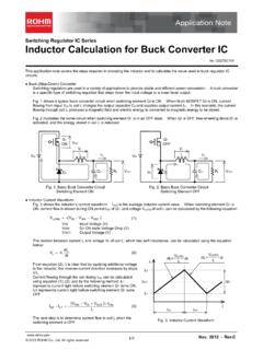
fscdn.rohm.comcircuits. Buck (Step-Down) Converter Switching regulators are used in a variety of applications to provide stable and efficient power conversion. A buck converter is a specific type of switching regulator that steps down the input voltage to a lower level output. Fig. 1 shows a typical buck converter circuit when switching element Q1 is ON.
Power Loss Calculation With CSI Consideration for ...
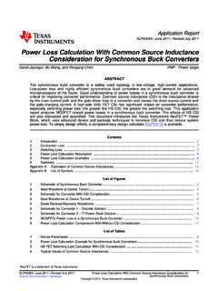
www.ti.comThe synchronous buck converter is a widely used topology in low-voltage, high-current applications. Low-power loss and highly efficient synchronous buck converters are in great demand for advanced microprocessors of the future. Good understanding of power losses in a synchronous buck converter is critical for improving converter performance.

Capacitor Calculation for Buck converter IC - Rohm
fscdn.rohm.comCapacitor Calculation for Buck converter IC This application note explains the calculation of external capacitor value for buck converter IC circuit. ... /2. To obtain more voltage margins, give consideration of using two 4.7µF / 50V capacitors in parallel. Also, be cautious for actual input ripple voltage that may get higher than the ...
DC-DC Power Converters - Auburn University
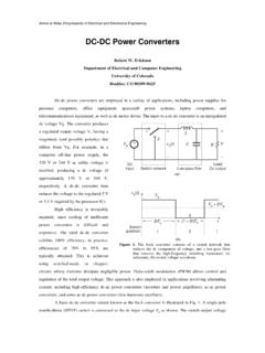
www.eng.auburn.eduThe first converter is the buck converter, which reduces the dc voltage and has conversion ratio M(D) = D. In a similar topology known as the boost converter, the positions of the switch and inductor are interchanged. This converter produces an output voltage V that is greater in magnitude than the input voltage V g

Snubber Circuit for Buck Converter IC : Power …
rohmfs.rohm.com1/5 © 2016 ROHM Co., Ltd. All rights reserved. www.rohm.com OCT. 2016 - Rev. 001 AEK59-D1-0311-0 Switching Regulator Series Snubber Circuit for Buck Converter IC In buck converter ICs, many high-frequency noises are
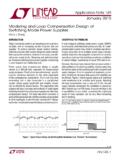
AN149 Modeling and Loop Compensation Design …
www.analog.comA N 149 AN149-5 an149fa By applying this two-step modeling technique to a buck converter, as shown in Figure 8, the buck converter power stage can be modeled as simple voltage source, dˆ • VIN,

Inductor Calculation for Buck Converter IC - Rohm
rohmfs.rohm.comApplication Note 3/4 www.rohm.com Nov. 2012 - Rev.C © 2012 ROHM Co., Ltd. All rights reserved. Inductor Calculation of Buck Converter Current-difference between max ...
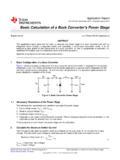
Basic Calculation of a Buck Converter's Power Stage (Rev. B)
www.ti.com(max) V Maximum Duty Cycle: D = V !´ OUT IN V IN V OUT IIN IOUT C IN C OUT L D SW Application Report SLVA477B–December 2011–Revised August 2015 Basic Calculation of a Buck Converter…

Reduction of the High-Frequency Switching Noise in the ...
ww1.microchip.comAN1466 DS01466B-page 4 2013 Microchip Technology Inc. FIGURE 5: Buck Converter’s AC Output. Measurement of the Ringing Frequency on a Two Layers 12V/5V MCP16301 Buck Converter.
Benefits of a multiphase buck converter - TI.com
www.ti.comHigh-Performance Analog Products www.ti.com/aaj 1Q 2012 Analog Applications Journal Texas Instruments Incorporated 8 Benefits of a multiphase buck converter ...
Basic Calculation of a Buck Converter's Power Stage (Rev. B)
www.ti.comInductor Ripple Current: !I = L - ´ f ´ Inductor Selection www.ti.com η= efficiency of the converter, e.g., estimated 90% The efficiency is added to the duty cycle calculation, because the converter also has to deliver the energy dissipated. This calculation gives a more realistic duty cycle than just the formula without the efficiency factor.

H-bridge motor controller design using Nexperia discrete ...
assets.nexperia.comThe buck converter consists of: Q5 (BUK6Y33-60P), Schottky diode D6 (PMEG10030ELP) and inductor L1. The output of the buck converter supplies the 12 V rail. When the output of U21 is high it turns on Q5 via the NPN transistor Q3 (BC846) and the NPN/ PNP dual transistor pair Q4 (BC846BPN). The voltage on node “V_12” will then increase. When

AN136 - PCB Layout Considerations for Non …
www.analog.comApplication Note 136 AN136-3 an136f Figure 3. Minimize the High di/dt Loop Area in the Synchronous Buck Converter. (a) High di/dt loop (Hot Loop) and its Parasitic PCB Inductors, (b) Layout Example

NCP81075 - Dual MOSFET Gate Driver, High Performance
www.onsemi.comMOSFETs in a synchronous buck converter. The NCP81075 uses an on−chip bootstrap diode to eliminate the external discrete diode. A high floating top driver design can accommodate HB voltage as high as 180 V. The low−side and high−side are independently controlled and match to 4 ns between the turn−on and turn−off of each other.
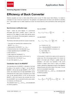
Efficiency of Buck Converter - Rohm
fscdn.rohm.comConduction loss caused by the on-resistance of the ... direction to the reverse bias state causes a diode recovery, which in turn generates a reverse recovery loss in the body diode. This loss is determined by the reverse recovery time of
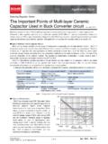
The Important Points of Multi-layer Ceramic …
rohmfs.rohm.comApplication Note 2 of 4 © 2013 ROHM Co., Ltd. All rights reserved. www.rohm.com Apr. 2013 - Rev.1.0 The Important Points of Multi-layer Ceramic Capacitor Used in Buck Converter circuit

BUCK Converter Control Cookbook - aosmd.com
www.aosmd.comBUCK Converter Control Cookbook Zach Zhang, Alpha & Omega Semiconductor, Inc. A Buck converter consists of the power stage and feedback control circuit. The power stage includes power switch and output filter. It converts a higher input voltage to a lower output voltage. The feedback control circuit regulates the output voltage by
Similar queries
AN-2292Designing an Isolated Buck Flybuck, Converter, Buck converter, Buck, Converter www.ti.com, Buck-boost converter, Boost converter, Circuits, Calculation, Capacitor, Parallel, Snubber Circuit for Buck Converter IC : Power, Snubber Circuit for Buck Converter IC, Modeling, Inductor Calculation for Buck Converter, The High-Frequency Switching Noise in, Texas Instruments, Inductor, Conduction, Reverse, Of Multi-layer Ceramic, Of Multi-layer Ceramic Capacitor Used, BUCK Converter Control Cookbook, Control