Probe Card Tutorial - Tektronix
making an epoxy card include probe tip shaping, planarity, final alignment, and QA processes. ... Beam length also influences contact force, but the relationship is inversely proportional, so increasing the beam length decreases contact force. The probe tip length and
Download Probe Card Tutorial - Tektronix

Information
Domain:
Source:
Link to this page:
Documents from same domain

P5200A Series High Voltage Differential Probes ...
download.tek.comHigh Voltage Differential Probes Installation and Safety Instructions & Product Documentation CD ZZZ *P071288902* 071-2889-02. ... To disconnect the probes, first disconnect the probe from the circuit. Next, turn ... P5200A Series High Voltage Differential. P5200A.
TDP0500 & TDP1000 High Voltage Differential Probes ...
download.tek.comWarranty Tektronix warrants that this product will be free from defects in materials and workmanship for a period of one (1) year from the date of

Analyzing 26-53 GBaud PAM4 Optical and Electrical Signals
download.tek.comWWW.TEK.COM | 7 Analyzing 26-53 GBaud PAM4 Optical and Electrical Signals APPICATIO OTE 3. Debugging PAM4 Systems and Transceivers Testing a transceiver for compliance to the specified

Understanding and Performing MIPI D-PHY Physical Layer ...
download.tek.comfrom a miniature circuit, the probes with a wide range of accessories like miniature tips, micro clips, solder-tips, etc are needed. For example, a P7360 probe with square pin adapter, and a probe-tip of P6780 (Partnumber 020-3035-00, kit of 15 …
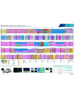
(Courtesy of Tektronix)
download.tek.comCELLULAR NETWORKS GENERATION TECHNOLOGY CHANNEL SPACING COMMON FREQUENCIES 5G NR - FR1 (New Radio - Frequency Range 1) 5 MHz 10 MHz 15 MHz 20 MHz 25 MHz 30 MHz 40 MHz 50 MHz 60 MHz 70 MHz ... 2100 MHz (IMT) 2300 MHz (S-Band) 2500 MHz (S-Band/BRS) 2600 MHz (IMT-E) 3500 MHz (C-Band) 3700 MHz (C-Band) 4700 MHz (C …

Model 2700 Multimeter/Switch System User's Manual
download.tek.comA good safety pr actice is to expect that hazardous voltage is present in any unknown circuit before measuring. Operators of this product must be protec ted from electric shock at all times. The responsible body must ensure that operators are prevented access and/or insulated from ever y connection point. In some cases, connections must be

2110 5½-Digit Dual-Display Digital Multimeter
download.tek.comRTD and NTC Thermistor Measurements: Accuracy ±0.8˚C, 1 year, exclusive of lead accuracy. PT100, D100, F100, PT385, PT3916, SPRTD (R-Zero, A4, B4, Ax, Bx, Cx, and Dx), NTCT (A, B, and C), and user-definable RTD. CAPACITANCE CHARACTERISTICS Range Test Current Accuracy1 ±(% of reading + % of range) 1 Year, 23° ±5°C 1000. nF 10 µA 2.0 + 0 ...

Datasheet KickStart
download.tek.comPlot and view multiple channels in a single graph with KickStart’s Data Logger App. Create personalized labels for each channel of your data logging switch card. DUT n DUT 2 DUT 1 The Data Logger app aids in the quick setup and control of …

Model 2000 6½-Digit Multimeter
download.tek.comA T ektr onix Company Datasheet Model 2000 6.5 Digit Multimeter DC OPERATING CHARACTERISTICS 2 Function Digits Readings/s PLCs 8 DCV (all ranges), 6½ 3, 4 5 10 DCI (all ranges), and 6½ 3, 7 30 1 Ohms (<10M range) 6½ 3, 5 50 1 5½ 3, 5 270 0.1 5½ 5 500 0.1 5½ 5 1000 0.04 4½ 5 2000 0.01 DC SYSTEM SPEEDS 2, 6 RANGE CHANGE 3: 50/s. FUNCTION …

オシロスコープのすべて - Tektronix
download.tek.com4 www.tektronix.com/ja/oscilloscopes 入門書 光電池 光源 図1 . .オシロスコープを使用した科学データ収集の例 はじめに 海の波 ...
Related documents

LRFD Beam Load Tables - cousesteel.com
www.cousesteel.comHow To Use The Beam Load Tables Example 1 A simply supported 20 in. x 12 in. x 3/8 in. ERW HSS beam of Fy = 46 ksi (ASTM A500 Gr. B) spans 22 feet. The beam is laterally braced for its entire length. Determine the uniform load capacity for loading in the plane of the minor axis. Enter the Fy = 46 load table for the HSS20x12x3/8 (page 6). Read

UniFi AC Mesh Datasheet
dl-origin.ubnt.comantenna1 for spot-beam coverage in high-density locations with numerous APs and clients, like a conference hall or event center. Directional Coverage, Outdoors The UAP-AC-M is versatile. You have the option to use a 5 GHz sector antenna2 (wide beam in the azimuth plane and narrow in the elevation plane) for broad outdoor coverage.

Betatrons - MIT
web.mit.edu4. Shaping of the voltage pulse shape is not important in the betatron. The beam is distributed uniformly around the transport tube; there is no need for longitudinal confinement. The betatron magnet is usually driven by a bipolar, harmonic voltage waveform that cycles the core between - Bs and +Bs.

Machining Processes - University of Rhode Island
personal.egr.uri.edubeam Gaseous or Vacuum Laser beam machining Electron beam machining Ion beam machining tool Machining Ultrasonic machining abrasive vibrations Jet cutting high pressure jet EDM ... shaping operations •Can have adverse effects on the surface quality and properties, unless carried out properly,

Technical White Paper Massive MIMO for New Radio
images.samsung.comCoverage enhancement and shaping - Pin-pointing the focused beam to a particular user located in the cell edge can improve the quality of received DL signal and increase cell coverage. Furthermore, because the signal power is highly focused on

14. Measuring Ultrashort Laser Pulses I: Autocorrelation
www.brown.eduthe return beam in space: But out-of-plane tilt yields a nonparallel return beam. Corner cubes involve three reflections and also displace the return beam in space. Even better, they always yield a parallel return beam: “Hollow corner cubes” avoid propagation through glass. Translation stage Input pulse E(t) E(t– ) Mirrors Output pulse

GENERAL NOTES HINGE POINT LINE - Wisconsin Department …
wisconsindot.govJul 13, 2018 · mgs beam guard (mgs) (see other details) direction of travel slope 10:1 or flatter to hinge point 2' - 0" offset 25:1 flareto face of rail slope 10:1 max. 5' - 0" min. to hinge point slope slope a 15:1 taper a gradeline variable slope 14 2' - 0" (at post no. 9) parallel with traveled way 4:1 taper 5' - 4" at post no. 5

Understanding ISO 21501-4
www.pmeasuring.comthe resultant light scattering peak as a particle passes through the laser beam. Resolution is improved if the particles are illuminated by the most uniform and highest intensity light. During instrument design and development, PMS optimizes resolution by integrating beam-shaping lenses and masks that can

Spatial Signal Processing (Beamforming)
www.personal.psu.edu• Beamforming can be accomplished physically (shaping and moving a transducer), electrically (analog delay circuitry), or mathematically (digital signal processing). ... • Beam steering – A beamformer can be electronically steered, with some degradation in performance.

HOLLOW STRUCTURAL SECTIONS - Bull Moose Tube
www.bullmoosetube.comSelect the lightest 7-inch deep, simply supported ERW HSS beam of Fy = 50 ksi (ASTM A500 Gr. C) to span 6 feet and support a load of 5.3 kips per foot (includes estimated weight of HSS beam). The beam is laterally supported for its entire length. Required total uniform load to be supported is equal to 31.8 kips (5.3 kips/ft. x 6 ft.)