
Product data sheets - ifm
Jan 31, 2017 · Connection: Round connector M 12 x 1 with switching status and operating voltage indication and self-locking screw coupling. In general, weld-immune switches have to be used in body-in-white applications. If aluminium or magnesium is to be detected, a switch with K = 1 has to be used (K = correction factor = reduction factor).
Download Product data sheets - ifm

Information
Domain:
Source:
Link to this page:
Documents from same domain

Schulungsunterlagen Induktive Sensoren - ifm
www.ifm.comSchulungsunterlagen 4 4 Induktive Näherungsschalter der ifm 56 4.1Mechanische Eigenschaften56 4.1.1Aufbau allgemein56 4.1.2Zeitliche Entwicklung56

ifm electronic Sensors, networking and control …
www.ifm.comR temperature sensors 1 Training manual ifm electronic Sensors, networking and control technology for automation Training manual R temperature sensors
Info card Operating voltage The voltage range in …
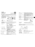
www.ifm.comUK Info card Inductive sensors 1 2 Operating voltage The voltage range in which the sensor functions reliably. A stabilised and smoothed direct voltage should be used!

Project: Melbourne Airport - ifm.com
www.ifm.comProject: Melbourne Airport Baggage conveyor system Authors: David D‘Souza Peter Wienzek ... transported to the correct baggage vehicle via turnouts and conveyor belts and then onto the corresponding aeroplane. ... Baggage conveyor belt with e-stops Fail-safe inductive sensors

Operating instructions Switching amplifier for fibre optics …
www.ifm.com4 3.1 Attaching the fibre optics 1 Loosen the screw (A) 2 Push the fibre optics into the sen-sor holes (B) until you feel a slight resistance (O-ring) 3 Push the fibre optics until the end
Info card Operating voltage The voltage range in which the ...
www.ifm.comUK Info card Inductive sensors 5 6 Electrical connection The unit must be connected by a qualified electrician. ①Use a miniature fuse according to the technical data sheet, if specified. Recommendation: Check the safe functioning of the unit after a short circuit.

ifm Fibel AS-Interface Ausg
www.ifm.comThis manual is intended to provide the user with basic information about the different ifm AS-i product families. * * * Everyone has probably experienced it already: during setup, the red LED [FAULT] is suddenly lit on the AS-i module and you are not sure if the module is faulty or if maybe it still has the slave address 0?

Know-How ecomatmobile - ifm
www.ifm.com• CANopen master • CANopen slave (V1) Version (Vxxyyzz) of the CRnnnn device's runtime system (V2) Version (Vnn) of the template The article number in the template must be exactly identical with the article number of the device to be programmed! → Device manual, chapter "Information concerning the software" >

Condition Monitoring Systems (CMS) in wind turbines CMS
www.ifm.comJul 22, 2010 · Condition Monitoring The digital alarm signals of efector octavis Main alarm Normal range - OK Pre-alarm ... Condition monitoring in wind parks via Ethernet / OPC interface Information on processor performance ... 2 diagnostic electronics VSE 1) monitoring bearing, converter 2) monitoring bearing, rotor ...
User Manual for PLC Programming - ifm
www.ifm.comAug 20, 2003 · Overview of CoDeSys Functions... 1-2 CoDeSys V2.3 You can use the flow control to check which program lines have been run. A Log records operations, user actions and internal processes during an online session in a chronological order. If activated in the target settings the Sampling Trace allows you to trace and display the actual course of variables over an …
Related documents

MIxIng vAlveS
www.apollovalves.companyFeb 27, 2014 · and includes: ball valves, butterfly valves, backflow prevention devices, water pressure reducing valves, mixing valves, safety relief valves, water gauges, strainers, vacuum breakers, valve actuators and more. Conbraco’s vertically integrated manufacturing ensures a consistency of production, testing, quality and availability.

Water Use Survey Cross Connection Control
greaterouachita.orgCross Connection Control . Greater Ouachita Water Company (GOWC) has developed a cross-connection control program (CCCP) to help eliminate potential cross-connections from the potable water supply. A cross-connection is the point at which a contaminated substance comes in contact with a drinking water system.

Florida Building Code 6 Edition (2017) Plumbing
www.broward.org312.10 Inspection and testing of backflow prevention assemblies. Inspection and testing shall comply with Sec-tions 312.10.1 and 312.10.2. 312.10.1 Inspections. Inspections shall be made of all backflow prevention assemblies and air gaps to determine whether they are operable. 312.10.2 Testing. Reduced pressure principle, double

OREGON ADMINISTRATIVE RULES OREGON HEALTH …
www.oregon.govBackflow Prevention Assembly, RPDA, Double Check Valve Backflow Prevention Assembly, Double Check- Detector Backflow Prevention Assembly, Pressure Vacuum Breaker Backsiphonage Prevention Assembly, or Spill-Resistant Pressure Vacuum Breaker Backsiphonage Prevention Assembly, of a make, model, orientation, and size approved by the …

Drinking Water Distribution Exam Expected Range of Knowledge
www.waterboards.ca.govCross-Connection and Backflow Devices D1 - D5 Knowledge of conditions that cause backflow D1 - D5 Knowledge of available backflow prevention methods D1 - D5 Knowledge of “back-pressure” and “back-siphonage” conditions . Expected Range of Knowledge for Drinking Water Distribution Exam 4
Please use a separate form for each assembly
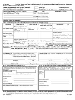
www1.nyc.govCross-Connection Control Unit 59-17 Junction Boulevard, 3rd Fl. Low-Rise, Flushing, NY 11373-5108 Refer to “NEW YORK CITY CROSS-CONNECTION CONTROL PROGRAM HANDBOOK”, latest version on DEP web site. NYC Rev. - GEN215B 1/201 9| DCN: BWSO-FRM- -201