
QUICK FUEL TECHNOLOGY® - Holley
Sep 11, 2019 · certain the voltage does not drop below 12.6 volts. (Some engines use a field wire from the alternator that only produces 9.5 volts which does not allow the choke to operate properly.) (-) Grounded to carburetor (+) Ignition activated 12V source STARTING THE ENGINE: 1. Reattach the negative battery cable. You are now ready to start the engine. 2.
Download QUICK FUEL TECHNOLOGY® - Holley

Information
Domain:
Source:
Link to this page:
Documents from same domain
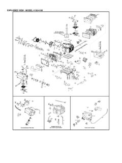
EXPLODED VIEW - MODEL 4150/4160 - Holley …
documents.holley.comNOMENCLATURE - MODEL 4150/4160 Ref. No. Description Ref. No. Description 1 Dashpot Nut 2 Dashpot Assembly 3 Da shpot Bracket Screw 4 Dashpot Bracket 5 Throttle Lever Extension Screw 6 Throttle Lever Extension Nut 7 Lockwasher Extension Nut 8 Throttle Lever Extension 9 Solenoid Bracket Screw 10 Solenoid Bracket Screw …
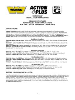
WATER PUMP INSTALLATION INSTRUCTIONS …
documents.holley.com1 water pump installation instructions weiand water pumps action plus & team g applications for small block & big block chevrolets applications:
Instruction Manual Addendum - Holley Performance Products
documents.holley.comInstruction Manual Addendum For Versions 3.35-3.38 Software ... and scroll down to “Fuel Injection”. Click on “Pro–Jection ... Chev350-1 – Generic TBI map. Used for engines with low peak horsepower rpm. Chev454 – Use on TBI systems with 85 lb/hr injectors. Calibrated on a 454 cubic inch
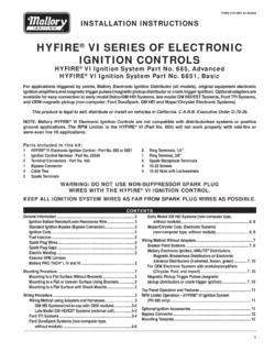
HYFIRE VI SERIES OF ELECTRONIC IGNITION CONTROLS
documents.holley.comHYFIRE® VI SERIES OF ELECTRONIC IGNITION CONTROLS ... Ignition Coils The HYFIRE ® VI Electronic Ignition Controls are designed to work with most original equipment ignition coils. For optimum performance use the Mallory PROMASTER ...
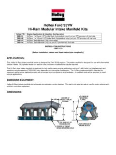
Holley Ford 351W Hi-Ram Modular Intake Manifold Kits
documents.holley.comHi-Ram Modular Intake Manifold Kits Holley P/N Engine Application & Induction Configuration ... This Holley Hi-Ram intake manifold series is designed for Ford 351W engines. This intake manifold is designed for use with aftermarket ... This Hi-Ram style intake manifold is designed for high performance engine applications up to 427-440 cubic inch ...
QUICKSTART MANUAL - Holley Performance
documents.holley.com2 INTRODUCTION & SYSTEM REQUIREMENTS Holley Performance Products has written this manual for the installation of the Sniper EFI TBI fuel injection system. This basic manual contains the information necessary for the installation of the throttle body, wiring, and sensors.
MSD Digital 6A and 6AL Ignition Control 6A - PN 6201/62013 ...
documents.holley.com4 INSTALLATION INSTRUCTIONS MSD • WWWMSDPERFORMANCECOM - FA - WIRING GENERAL WIRING INFORMATION Wire Length: All of the wires of the MSD Ignition may be shortened as long as quality connectors are used or soldered in place. To lengthen the …
Programmable Digital-7 Plus PN 7531
documents.holley.comINSTALLATION INSTRUCTIONS 3 S UÊ WWW.MSDPERFORMANCE.COM Ê UÊ £x® Ê nxÇ xÓää Ê UÊ 8 Ê £x® Ê nxÇ ÎÎ{{ Limit Lt Green Accessories Dark Blue This wire activates the Launch Rev Limit and is the main reset wire for several features of the Ignition. When 12 volts are applied to this wire it will activate the Launch Rev Limit.
LAKEWOOD/QUICKTIME SAFETY BELLHOUSING
documents.holley.com6 www.lakewood-industries.com LAKEWOOD IS A TRADEMARK OF PRESTOLITE PERFORMANCE family of brands 10601 MEMPHIS AVE. #12, CLEVELAND, OH 44144 • 216.688.8300 Form #INSTBELL 06/13 Printed in U.S.A. CHRYSLER/MOPAR BELLHOUSINGS
EXPLODED VIEW - MODEL 4150/4160 - Holley Performance
documents.holley.comNOMENCLATURE - MODEL 4150/4160 Ref. No. Description Ref. No. Description 1 Dashpot Nut 2 Dashpot Assembly 3 Da shpot Bracket Screw 4 Dashpot Bracket 5 Throttle Lever Extension Screw 6 Throttle Lever Extension Nut 7 Lockwasher Extension Nut 8 Throttle Lever Extension 9 Solenoid Bracket Screw 10 Solenoid Bracket Screw 11 Solenoid Bracket 12 Solenoid Assembly
Related documents

How To Wire Alternator - gearheadswc.com
gearheadswc.comnegative ground and the alternator regulator may be damaged if it is wired as positive ground. Step #10 Start engine and test alternator. While engine is at idle, take a screwdriver or
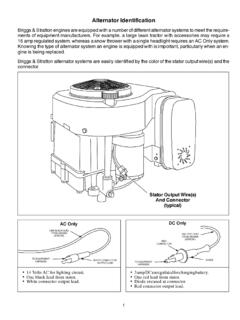
Alternator Identification
www.smallenginesuppliers.comthe alternator output must be very evenly matched to the equipment requirements. When replacing an engine in these applications, the alternator must be the same as the original.

ELECTRONIC ENGINE CONTROLLER - Chrysler
starparts.chrysler.com• Charging system malfunction: Alternator defective or battery not fully charged. NOTE: In 1985 and later vehicles, the voltage regulator is controlled by BOTH the Logic and Power modules. In many vehicles, the voltage regulator is in the alternator.
Understanding the Alternator - Autoshop 101
www.autoshop101.comUnderstanding the Alternator • Four wires connect the alternator to the rest of the charging system. • B is the alternator output wire that supplies current to the battery. • IG is the ignition input that turns on the alternator/regulator assembly. • S is used by the regulator to monitor charging voltage at the battery.

Installation Manual - Compustar
geeksquad.compustar.comSTEP 2: Test wire and make connection. The stator wire is found at the vehicle’s alternator. Change your meter to DC before testing for this wire. A. At rest, with the ignition off, the stator wire should test 0V DC. B. Turn the ignition to the run position. The stator wire should now test between 1 – 6V DC.
Chapter 29 – Electromagnetic Induction
physics.ucf.eduslide-wire generator). The induced current tries to preserve the “status quo” by opposing motion or a change of flux. B induced downward opposing the change in flux (d Φ/dt). This leads to induced current clockwise.

6-Pin Wire Harness Assembly Adapter wire Installation …
www.briggsandstratton.comAlternator System 696576 ΠModels 400000/440000 OHV (Models equipped with Engine Minder ) Magnetron Armature Fuel Solenoid Ground Alternator System (over) 6-Pin Wire Harness Assembly Adapter wire Installation Guide Connect leads as shown per your service part number. An adapter wire, illustrated, may be required when connecting the alternator ...

Wiring Instructions for 60-0-60 Ammeter
www.fwmurphy.com) wire, minimum, with an insulation temperature rating of 220° F (105° C), minimum, from the battery terminal of the alternator to the left terminal on the ammeter (see wiring diagram).

Wire Harness Installation Instructions - Painless Performance
www.painlessperformance.comalternator exciter wire, distributor, water temperature, oil pressure, and air conditioning. DASH GROUP Includes wires to connect gauges, indicator lights, and switches to their proper sources.