Routing DDR4 Interfaces Quickly and Efficiently
Design rules above are for reference only and should be treated as such—only tried and true way to determine interface design rules is with pre- /post-route simulations DDR4 Design Rules
Download Routing DDR4 Interfaces Quickly and Efficiently

Information
Domain:
Source:
Link to this page:
Documents from same domain
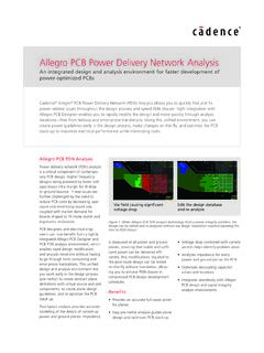
Allegro PCB Power Delivery Network Analysis - Cadence
www.cadence.comAllegro PCB Power Delivery Network Analysis Cadence is transforming the global electronics industry through a vision called EDA360. With an application-driven approach to design, our software, hardware, IP, and services help

Innovus Implementation System
www.cadence.comprofile of the paths and performing the placement adjustments based on these timing slacks. ... topology-based wire length, and congestion. It also integrates the mathe- ... automatically adding density screens in floorplan-induced high traffic areas. The algorithm analyzes floorplans, traffic ...

Holistic FMEDA-Driven Safety Design and Verification for ...
www.cadence.comThe integration of these ... In recent years, safety design and verification for digital circuits have made great progress. However, more than 80% of field failures are due to the analog or mixed-signal portion of products [4]. Hence the safety methodology must be enhanced to ... deployed later in the SoC design process.

Chiplets and Heterogeneous Packaging Are Changing System ...
www.cadence.comChiplets and Heterogeneous Packaging Are Changing System Design and Analysis www.cadence.com 2 Introduction The semiconductor packaging industry is now poised to take on a larger, more significant role in electronic product design of the future. To meet the market demand for these heterogenous, chiplet-based architectures (Figure 1), new system ...

Master Learning Maps - cadence.com
www.cadence.comBehavioral Modeling with VHDL-AMS Command-Line Based Mixed-Signal Simulations w/ Xcelium r Use Model r Circuit Design, Simulation, Modeling and RF Design Custom IC, Analog and RF Design Learning MapLearning Map Digital Design and Signoff Mixed-Signal Simulations using Spectre AMS Designer Analog Modeling with Verilog-A Behavioral Modeling with ...

Keeping Things Quiet: A New Methodology for Dynamic ...
www.cadence.comVirtuoso AMS Designer Mixed-signal verification with Incisive® solution Virtuoso® Analog Design Environment (ADE) Simulation environment Liberate™ Solution Characterization Voltus™-FI Solution EMIR

DO-254 Explained
www.cadence.comstandard used on commercial electronics that go into aircraft. (Conceptually speaking, this standard applies to all electronics in anything that flies or could crash and pose a hazard to the public.) DO-254 Explained By Cadence This white paper, the first in a series of DO-254-related white papers, will explore the high-level concepts

Integrated Metrics Center Technical Brief
www.cadence.comcoverage—block, expression, toggle, and finite state machine (FSM)—as well as assertion and functional coverage. An activity center consists of a coverage metrics window, a source code window, an attributes window, and often, depending on the type of metric, an additional deep-dive analysis window. The
Related documents

Layout Design Guide - Toradex
docs.toradex.comLayout Design Guide Toradex AG l Altsagenstrasse 5 l 6048 Horw l Switzerland l +41 41 500 48 00 l www.toradex.com l info@toradex.com Page | 2 Issued by: Toradex Document Type: Design Guide Purpose: This document is a guideline for designing a carrier board with high speed signals that is used with Toradex Computer Modules. Document

Board Design Guidelines for PCI Express™ Architecture
e2e.ti.comTrace LengthTrace Length §Longer trace length ⇒ loss ↑ ü~0.25 to 0.35 dB inherent loss per inch for FR4 microstrip traces at 1.25GHz §Manage trace lengths to minimize loss üExample: 12” board, 3.5” add-in card lengths Example VNA measurements for differential mstrip trace insertion loss -5.23dB 1.25GHz 20-inch line freq dB Layout ...

AN-111
ww1.microchip.comDifferential Signal Layout • Differential pair (TX+/- or RX+/-) should be routed away from all other signals and close together to use 5-mil trace width and 5-mil trace space in same length as possible with 100 ohms controlled trace. • Keep both traces of each differential pair as identical to each other as possible.

Introduction Differential Traces
www.intel.comW width of a single trace in a differential pair S space between two traces of a differential pair D space between two adjacent differential pairs B thickness of the board For good coupling between two conductors of a differential pair, the following rules should be followed:

AN3940, Hardware and Layout Design Considerations for …
www.nxp.comHardware and Layout Design Considerations for DDR3 SDRAM Memory Interfaces, Rev. 6 Freescale Semiconductor 5 DDR3 designer checklist 30. Note: Some product implementations may support only the single-ended version of the strobe. † Match all segment lengths between differential pairs along the entire length of the pair.

AN5097, Hardware and Layout Design Considerations for …
www.nxp.compair. Trace match the MDQS/MDQS pair to be within +/-5 mils. • Maintain constant line impedance along the routing path by maintaining the required line width and trace separation for the given stackup. • Avoid routing differential pairs adjacent to noisy signal lines or high-speed switching devices such as clock chips.

High-Speed Layout Guidelines for Signal Conditioners and ...
www.ti.com3.1 Trace Impedance For high speed signals trace impedance needs to designed as to minimize the reflections in traces. There are two types of trace impedance that need to be taken into consideration when designing high speed signals. Single ended impedance is the trace impedance with reference to ground. Differential Impedance

Xilinx UG393 Spartan-6 FPGA PCB Design Guide
www.xilinx.comSpartan-6 FPGA PCB Design and Pin Planning www.xilinx.com UG393 (v1.3) October 17, 2012 Xilinx is disclosing this user guide, manual, release note, and/ or specification (the "Documentation") to you solely for use in the development