SERVICE MANUAL - Navistar
3200, 4100, 4200, 4300, 4400, 7300, 7400, 7500, 7600, 7700, 8500, 8600, MXT, RXT Models Built Oct. 1, 2005 to Feb. 28, 2007 — ELECTRICAL CIRCUIT DIAGRAMS
Download SERVICE MANUAL - Navistar

Information
Domain:
Source:
Link to this page:
Documents from same domain

MaxxForce 11 and 13 (2010) - Navistar
bodybuilder.navistar.comNAV_IST_030711 Idle Shut Down Timer ©2011 Navistar, Inc. MaxxForce 11 and 13 (2010) Overview: Idle Shutdown Timer (including Certified Clean Idle)
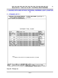
7. GAUGES WITH AND WITHOUT INTEGRAL …
bodybuilder.navistar.com3200, 4100, 4200, 4300, 4400, 7300, 7400, 7500, 7600, 7700, 8500, 8600, MXT, RXT Models Built Oct. 1, 2005 to Feb. 28, 2007 — ELECTRICAL CIRCUIT DIAGRAMS

Component Information 2004 - Navistar
bodybuilder.navistar.comComponent Information 2004 4000 Models Body Builder Data ECM2 Electronic Engine Control Features and Programmable Parameters For International

SERVICE MANUAL - Navistar
bodybuilder.navistar.comLoneStar® and ProStar® Chassis Built January, 2007 and After — ELECTRICAL CIRCUIT DIAGRAMS iii 4.44. REMOTE RADIO — N/AMP AND N/WIRED REMOTE AND N/DRIVER INTERFACE DISPLAY,
CF 500, CF 600 Circuit Diagrams - Navistar
bodybuilder.navistar.comIntroduction p 3-5 Component and Connector Information Cell 152 “Component Location Charts” helps the user find where the various items depicted on the schematic can physically be found on the

SERVICE MANUAL SECTION BODY CONTROLLER …
bodybuilder.navistar.comBODY CONTROLLER DIAGNOSTIC TROUBLE CODES (S08327) 1. DEFINITIONS 1.1.2. Displaying Codes on the VID (if equipped) The VID can be used to display all diagnostic trouble codes (DTC) on the vehicle. Suspect parameter number (SPN), failure mode indicator (FMI) and occurrence count numbers are listed. Source addresses and DTC
SERVICE MANUAL - Navistar
bodybuilder.navistar.com3200, 4200, 4300, 4400, 7300, 7400, 7500, 7600, 8500, 8600 SERIES Built After March 10, 2004 — ELECTRICAL CIRCUIT DIAGRAMS i Table of Contents

SERVICE MANUAL - Navistar
bodybuilder.navistar.com4200, 4300, 4400 series built october 16, 2000 to december 31, 2001 — electrical circuit diagrams 1 1. instructions and charts (chapter 1) 1.1. circuit number identification and location chart, p. 1

SERVICE MANUAL
bodybuilder.navistar.com3200, 4200, 4300, 4400, 7300, 7400, 7500, 7600, 8500, 8600 SERIES Built October 1, 2002 and After — ELECTRICAL CIRCUIT DIAGRAMS i Table of Contents

SERVICE MANUAL - Navistar
bodybuilder.navistar.com3200, 4100, 4200, 4300, 4400, 7300, 7400, 7500, 7600, 7700, 8500, 8600, MXT, RXT Models Built Oct. 1, 2005 to Feb. 28, 2007 — ELECTRICAL CIRCUIT DIAGRAMS
Related documents
> Port size: 1/4” 1/2” > Control of pneumatic (ISO G / NPT ...
cdn.norgren.comValve body, trim, coil housing and top cover: stainless steel 1.4404 (316 L) O-rings seats & seals: NBR Other seal materials available on request. Technical features > Port size: 1/4”... 1/2” (ISO G / NPT) Namur or manifold > Direct acting solenoid valve > High flow > 12 bar inlet pressure > Reliable and long life, ideal for a one time ...
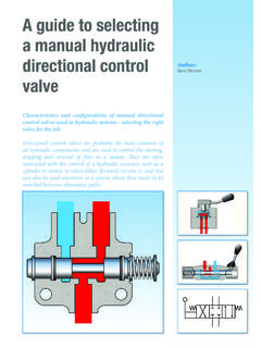
A guide to selecting a manual hydraulic directional ...
www.grouphes.comthe body. The size of the clearance between spool and body is always a compromise between enabling the spool to slide freely without sticking (especially important for spring return spools) and reducing the leakage through the clearance to a minimum. In practice therefore, for a 75 l/min (20 gpm) rated flow valve, leakage rates (from P

OWNER’S MANUAL - .NET Framework
mymarshall.blob.core.windows.net(#9 in this manual). POWER AMPLIFIERS MST modelling recreates four classic and vintage valve power output topologies. A valve power stage is a vital part of an all-valve amplifier’s sound and its tonal character. SPEAKER CABINETS Marshall speaker cabinets are perhaps as famous as Marshall amplifiers. The iconic 4 x 12”

Instruction Manual Fisher GX Control Valve Actuator System
www.emerson.comthe valve body construction is selected. The GX meets the requirements of both EN and ASME standards. It is available with a complete accessory package, including the FIELDVUE DVC2000 integrated digital valve controller. Instruction Manual …

Installation and Service Guide - H2O Distributors
www.h2odistributors.com4. Move the tubing away from the valve to make room for the John Guest Angle Stop Valve. 5. Connect the swivel end of the John Guest Angle Stop Valve to the threads on the cold water shut-off. This connection should only be hand tight. 6. Connect the riser tube to the male end of the John Guest Angle Stop Valve and tighten with a wrench. 7.

69-2631ES 03 - HE360 Humidifier and Installation Kit
www.honeywellstore.com• Do not locate the humidifier on the furnace body. • Allow adequate clearance in front of and above the humidifier so you can easily remove the cover to perform routine maintenance. — Mount the humidifier at least 3 in. (78 mm) above the furnace body to allow adequate space for the solenoid valve and drain line.

Dry System Technical Manual for Operation, Maintenance …
www.vikinggroupinc.comvalve will open and relieve the priming pressure from the internal diaphragm as-sembly. The internal diaphragm assembly will compress, which will allow water to pass through the body of the valve and center of the internal check valve, entering the sprinkler system piping. Figure 4a