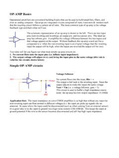
Simple OP-AMP circuits
Application hint: Use precision resistors. If the two R2 resistors differ by 1% you're difference will be off by 1%. Same goes for the R1 resistors. Assume V1 = V2. If the resistors aren't matched the output won't be zero. Actually, it's better to buy a difference amplifier or an instrumentation amplifier instead of building the difference amp
Download Simple OP-AMP circuits

Information
Domain:
Source:
Link to this page:
Documents from same domain
power supply info 2 - UNLV Physics & Astronomy
www.physics.unlv.eduhotter it gets the sooner the part will fail. You could also burn yourself if you touch the regulator (the case temp would be 25°C + 65°C/W * 1.2W = 103°C (217°F).
How to read an op-amp data sheet - UNLV Physics …
www.physics.unlv.eduHow to read an op-amp data sheet: We'll use the LM741: http://media.digikey.com/pdf/Data%20Sheets/Fairchild%20PDFs/LM741.pdf datasheet to explain the various specifications
Relay Basics - Astronomy
www.physics.unlv.eduRelay Basics: A relay is an electrical switch that uses an electromagnet to move the switch from the off to on position instead of a person moving the switch.
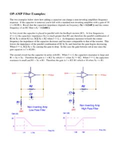
OP-AMP Filter Examples - Astronomy
www.physics.unlv.eduOP-AMP Filter Examples: The two examples below show how adding a capacitor can change a non-inverting amplifiers frequency response. If the capacitor is removed you're left with a standard non-inverting amplifier with a gain of 10
OP-AMP Filter Examples - UNLV Physics & Astronomy
www.physics.unlv.eduresponse. If the capacitor is removed you're left with a standard non-inverting amplifier with a gain of 10 (1 + R2/R1). Recall that the capacitors impedance depends on frequency (Xc = 1/(2πfC)) and the corner frequency of an RC filter is fc = 1/(2πRC). In first circuit the capacitor is placed in parallel with the feedback resistor (R2).
Related documents

a Instrumentation Amplifier Precision AD624
www.analog.comPrecision Instrumentation Amplifier PRODUCT DESCRIPTION The AD624 is a high precision, low noise, instrumentation amplifier designed primarily for use with low level transducers, including load cells, strain gauges and pressure transducers. An outstanding …
Strain Gage Instrumentation
www.vishaypg.comStrain Gage Instrumentation Vishay Precision Group Micro-Measurements P.O. Box 27777 Raleigh, NC 27611 U.S.A. Phone: +1-919-365-3800 Fax: +1-919-365-3945 www.micro-measurements.com

Analog Discovery 2™ Reference Manual
digilent.comStereo audio amplifier to drive external headphones or speakers with replicated AWG signals 16-channel pattern generator (3.3V CMOS, 100Msample/sec)i ii 16-channel virtual digital I/O including buttons, switches, and LEDs – perfect for logic training applicationsiii iv 16-channel digital logic analyzer (3.3V CMOS,

MCP6N16 - Microchip Technology
ww1.microchip.comMCP6N16 DS20005318A-page 2 2014 Microchip Technology Inc. Minimum Gain Options Table 1 shows key specifications that differentiate between the different minimum gain (GMIN) options. See Section 1.0 “Electrical Characteristics”, Section 6.0 “Packaging Information” and Product Identification System for further information on GMIN. Figures 1 to3 show input offset voltage …
MCP4728 - 12-Bit, Quad Digital-to-Analog Converter with ...
ww1.microchip.comAug 04, 2010 · • Instrumentation • Bias Voltage Adjustment for Power Amplifiers Description The MCP4728 device is a quad, 12-bit voltage output Digital-to-Analog Convertor (DAC) with nonvolatile memory (EEPROM). Its on-board precision output amplifier allows it to achieve rail-to-rail analog output swing. The DAC input codes, device configuration bits, and
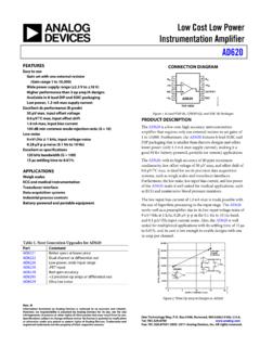
Low Cost Low Power Instrumentation Amplifier AD620
www.analog.comAD620 is a low cost, high accuracy instrumentation amplifier that requires only one external resistor to set gains of 1 to 10,000. Furthermore, the AD620 features 8-lead SOIC and DIP packaging that is smaller than discrete designs and offers lower power (only 1.3 mA max supply current), making it a

A Designer’s Guide to Instrumentation Amplifiers, 3rd Edition
www.analog.comtion applications are instrumentation amplifiers, and by no means are all in-amps used only in instrumentation applications. In-amps are used in many applications, from motor control to data acquisition to automotive. The intent of this guide is to explain the fundamentals of what an instrumentation amplifier is, how it operates,
Medical Instrumentation
www.egr.msu.eduECE 445: Biomedical Instrumentation Ch1 Basics. p. 18 Compensation: Negative Feedback • When modifying input cannot be avoided, negative feedback is used to make the output less dependent on the transfer function of the device • Feedback devices must be accurate and linear Amplifier Feedback - +

Electrocardiography Circuit Design
www.egr.msu.eduApr 05, 2013 · A basic three-op-amp instrumentation amplifier is shown in Figure 3. Figure 3: Basic Instrumentation Amplifier . 5 There are two stages for the instrumentation amplifier that help make it meet the ... A precision low-level DAS/ECG Cardiotachometer Demo Board, a
Precision Rectifier Circuits - Engineering
www.site.uottawa.caFor example, in instrumentation applications, the signal to be rectified can be of very small amplitude, say 0.1 V, making it impossible to employ the conventional rectifier circuits. Also the need arises ... amplifier with the inverting precision half-wave rectifier to get the precision full wave rectifier in the following page.