
Single Sideband Modulation (SSB)
blocking out the DC component. 29 Single Sideband Modulation (SSB) Standard AM and DSB-SC techniques are wasteful of bandwidth because they both require transmission bandwidth of 2B Hz, where B is the bandwidth of the baseband modulating signal m(t). ... Local oscillator
Download Single Sideband Modulation (SSB)

Information
Domain:
Source:
Link to this page:
Documents from same domain

Chap 3 : Two Random Variables
www.ee.ryerson.caChap 3: Two Random Variables Chap 3 : Two Random Variables Chap 3.1: Distribution Functions of Two RVs In many experiments, the observations are expressible not as a single quantity, but as a family of quantities. For example to record the height and weight of each person in a community or

ELE745 Assignment and Lab Manual - Ryerson University
www.ee.ryerson.ca) times the convolution of their spectra. From width property of the convolution, the width of the convoluted signals is the sum of the widths of the signals convolved. Therefore, the BW of the product is 25+50=75 Hz. The Nyquist rate is 150 Hz. 3. Lathi 6.1-4: The BW of the signal g(t) is 5 Hz (10… rad/s), since the FT as below: g(t) = sinc2 ...
Ph.D. Progress Report --- Report #2
www.ee.ryerson.caPh.D. Progress Report --- Report #2 (March 2001 -- March 2002) by Andy Gean Ye This report summarizes my Ph.D. research progress from March 2001 to March 2002. This time period corresponds to part of the third and fourth year of my Ph.D. candidacy. As stated in my first
Experiment 2: Amplitude Modulation and Demodulation
www.ee.ryerson.caHilbert transform based structure shown in Figure (2). Both detector structures are implemented in Matlab/Simulink. The AM signal to be demodulated is generated as in Part-A of this experiment. This signal is fed to both the oscilloscope and the sound …
Related documents

Nonblocking Assignments in Verilog Synthesis, Coding ...
www.sunburst-design.comJul 07, 2016 · Example 1 - Feedback oscillator with blocking assignments According to the IEEE Verilog Standard, the two always blocks can be scheduled in any order. If the first always block executes first after a reset, both y1 and y2 will take on the value of 1. If the second always block executes first after a reset, both y1 and y2 will take on the value 0.

Not Recommended for New - Silicon Labs
www.silabs.comISleepRC RC Oscillator/WUT ON and all register values main-tained, and all other blocks OFF — 900 — nA ISleepXO Sleep current using an external 32 kHz crystal. 2 — 1.7 — μA ISensor -LBD Low battery detector ON, register values maintained, and all other blocks OFF —1—μA IReady Crystal Oscillator and Main Digital Regulator ON, all ...
Datasheet - S2-LP - Ultra-low power, high performance, sub ...
www.st.com1 Description. The S2-LP is a high performance ultra-low power RF transceiver, intended for RF wireless applications in the sub-1 GHz band. It is designed to operate in both the license-free ISM and SRD frequency bands at 433, 512,
Capacitive Proximity Sensors Theory of Operation
www.softnoze.comsensor the oscillator’s amplitude decreases, switching the sensor output back to its original state. 55 ... An object in the blocking range prevents identification of a target in the operating range. There is a signal output assigned to both the operating range

KSZ8863MLL/FLL/RLL Integrated 3-Port 10/100 Managed …
ww1.microchip.com25 MHz or 50 MHz crystal or oscillator clock connections. Pins (X1 and X2) connect to a crystal. If an oscillator is used, X1 connects to a 3.3V tolerant oscillator, and X2 is a NC. Note: The clock is ±50 ppm for both crystal and oscillator. The clock should 15 X2 O be applied to X1 pin before the reset voltage goes high.
High Frequency VCO Design and Schematics
www.qsl.netwhich any oscillator accomplishes this goal can be judged based on the second harmonic output level of the oscillator. • A good oscillator should exhibit 2nd harmonic levels on the order of -40dBc. Another useful indicator of good oscillator design is the change in oscillation frequency versus DC bias reduction.

Using the 16 MHz Crystal Oscillator
www.nxp.comUsing the 16 MHz Crystal Oscillator Application Note, Rev. 1 Freescale Semiconductor 5 4 Enabling the On-Chip 16 MHz Oscillator To use the on-chip 16 MHz oscillator with a crystal, you must use a high quality crystal with an ESR below 20 ohms. To enable the on-chip 16 MH z oscillator, the Clock Source Cont rol Register (CSCR) must have
Handbook of Operational Amplifier Applications (Rev. B)
www.ti.comApplication Report S 1 HANDBOOK OF OPERATIONAL AMPLIFIER APPLICATIONS Bruce Carter and Thomas R. Brown ABSTRACT While in the process of reviewing Texas Instruments applications notes, including those
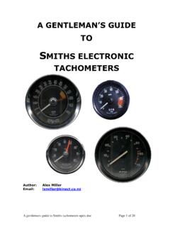
A gentlemans guide to Smiths tachometers updx
www.triumphclub.co.nza single transistor in a blocking oscillator circuit. The transformer primary winding was inside the case and connected to the car via two bullet connectors – one male, one female – mounted on the rear of the case. Generation 3 (RVC) – sensed voltage spikes at the coil to trigger the instrument. An integrated circuit is used to drive the ...