SLAB DESIGN - Memphis
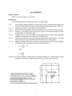
of the beam in the two directions must be related as follows: 2 12 2 21 0.2 5.0 l l α α ≤≤ where cb b cs s EI EI α= is the ratio of flexural stiffness of beam sections to flexural stiffness of a width of slab bounded laterally by center lines of adjacent panels (if any) on each side of the beam.
Download SLAB DESIGN - Memphis

Information
Domain:
Source:
Link to this page:
Documents from same domain
Chapter 11 SEISMIC DESIGN CRITERIA - Civil …
www.ce.memphis.eduP1: JsY ASCE003-11.tex ASCE003/SIE-v1.cls September 29, 2005 17:5 Chapter 11 SEISMIC DESIGN CRITERIA 11.1 GENERAL 11.1.1 Purpose. Chapter 11 presents criteria for the design and
Chapter 6. Compression Reinforcement - Flexural …
www.ce.memphis.eduCIVL 4135 118 Compression Reinforcement Chapter 6. Compression Reinforcement - Flexural Members Ifabeamcrosssectionislimitedbecauseofarchitecturalorotherconsiderations,itmayhap-

Review of Engineering Fundamentals - University …
www.ce.memphis.eduReview of Engineering Fundamentals CIVL 4197. Course Format ... FE Chemical 853 77% FE Civil 4,874 70% FE Electrical & Computer 1,217 …

ASCE Requirements for Citations f13 - Civil …
www.ce.memphis.eduASCE Requirements for Citations Books Feld, J. and Carper, K. (1997). Construction Failure, 2nd Ed., Wiley, New York. Book references must include author, book title, publisher, and the publisher’s

2 - Aggregate Gradation and Sampling - Civil …
www.ce.memphis.eduCIVL 3137 3 Gradation Analysis percent coarser or percent retained percent finer or percent passing
BEAM DESIGN - University of Memphis
www.ce.memphis.edu6 2. SHEAR DESIGN IN FLAT PLATES AND FLAT SLABS When two-way slabs are supported directly by columns, as in flat slabs and flat plates, or when slabs carry concentrated loads, as in footings, shear near the columns is of critical

Topic 14 - Foundation Design - Civil Engineering
www.ce.memphis.eduInstructional Materials Complementing FEMA 451, Design Examples Foundation Design 14-7 Reinforced Concrete Footings: Basic Design Criteria (concentrically loaded) d/2 …
Curing Concrete, Chapter 12 - The University of …
www.ce.memphis.edu221 Chapter 12 Curing Concrete 3. Methods that accelerate strength gain by supplying heat and additional moisture to the concrete. This is usually accomplished with live steam, heating coils,
AAA CE4135 ver2 - Civil Engineering
www.ce.memphis.eduCIVL 4135 Chapter 1. Introduction • 2 A problem unique to the design of reinforced concrete structures is the need to detail each member throughout.
Aggregates for Concrete - Department of Civil …
www.ce.memphis.eduT 27). The range of particle sizes in aggregate is illustrated in Fig. 5-4. The aggregate particle size is determined by using wire-mesh sieves with square openings.
Related documents
Chapter 2 Design for Shear - Engineering
by.genie.uottawa.ca2 units and beam dimensions in inches, nominal shear strength V c = 2√fc’bwd in units of lb. Shear reinforcement is not required for slabs, which can be considered as very wide beams. If the width of a beam is more than twice the thickness h of the beam, ACI 318-05, Section 11.5.6.1(c) exempts
BEAM-COLUMNS - UERJ
www.labciv.eng.uerj.brBEAM-COLUMNS SUMMARY: • Structural members subjected to axial compression and bending are known as beam columns. • The interaction of normal force and bending may be treated elastically or plastically using equilibrium for the classification of cross-section. • The behaviour and design of beam-columns are presented within the context of members subjected
22 COMPOSITE BEAMS – II
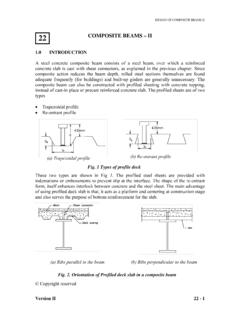
www.steel-insdag.orgFig. 5. Parallel beam grillage The primary or spine beams also achieve continuity by being used in pairs with one beam passing on either side of the columns. Shear is transferred into the columns by means of brackets. This ‘offset’ construction, where …
DESIGN OF AXIALLY LOADED COLUMNS
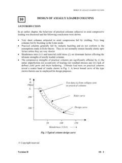
www.steel-insdag.org3.1 Stocky Columns It has been shown previously that very stocky columns (e.g. stub columns) resisted loads in excess of their squash load of fy.A (i.e. theoretical yield stress multiplied by the area of the column). This is because the effect of strain hardening is …

Glued laminated Beam desiGn taBles - Public.Resource.Org
law.resource.orgThe cantilever beam tables presented are applicable to balanced layups, such as 24F-V8 for Douglas-fir and 24F-V5 for southern pine, for three different systems. See Figure 2 for details of the following typical cantilever systems: • System 1 is a two-equal-span cantilever system with the cantilevered beam extending past the center support by

H-Beam
steelmatech.combending moment experienced by the beam. Beam theory shows that the H-shaped sections is a very efficient form for carrying both bending and shear loads in the plane of the web. H-beams are widely used in the construction industry and are available in a variety of standard sizes. H-beams may be used both as beams and as columns.

The Effective Length of Columns in Unbraced Frames
www.aisc.orgthe columns due to beam gravity load do not significantly affect overall frame stability in the elastic range.2 Most engineers use the alignment chart shown in Fig. 2, which provides approximate elastic solutions (A-factors) in lieu of an actual stability analysis (which

Stability of Steel beamS and columnS
www.steelconstruction.infobeams and columns – common cases of restraint (P093) written by Professors David ... 3.3 Beam supported at bottom flange only at the ends 33 3.4 Beams notched at the ends 34 3.5 Beams with intermediate restraint to compression flange 37 3.6 Beams with discrete intermediate restraints below top flange 39 3.7 Braced pairs of beams 40