Solderability Tests for Component Leads, Terminations ...
Solderability Tests for Component Leads, Terminations, Lugs, Terminals and Wires 1 PREFACE 1.1 Scope This standard prescribes test methods, defect definitions, acceptance criteria, and illustrations for assessing the solderability of electronic component leads, terminations, solid wires, stranded wires, lugs, and tabs.
Download Solderability Tests for Component Leads, Terminations ...

Information
Domain:
Source:
Link to this page:
Documents from same domain

Exigences et critères d’acceptabilité pour l ...
www.ipc.orgB.J. Franco, Honeywell Aerospace Richard Rumas, Honeywell Canada John Mastorides, Honeywell International William Novak, Honeywell International

A standard developed by IPC
www.ipc.orgIPC/WHMA-A-620B-S 2013 - June Space Applications Electronic Hardware Addendum to IPC/WHMA-A-620B Supersedes IPC/WHMA-A-620AS with Amendment 1 June 2012

Appendix B RoHS Substances and Exemptions List …
www.ipc.orgMarch 2011 IPC-1752A Appendix B RoHS Substances and Exemptions List The EU RoHS Directive continues to be updated over time. As these changes are made, the most current exemption list will

JOINT INDUSTRY GUIDE (JIG) - IPC
www.ipc.orgJOINT INDUSTRY GUIDE (JIG) Material Composition Declaration for Electrotechnical Products JIG-101 Ed 4.0 (Revision of JIG-101 Ed. 3.1, September 2010)

(Mechanical, Electrical, Environmental and Quality ...
www.ipc.orgIPC-9591 Performance Parameters (Mechanical, Electrical, Environmental and Quality/Reliability) for Air Moving Devices Developed by the Air Moving Devices Standard Subcommitte (9-81) of

Certification Quality Initiative User’s Guide v
www.ipc.orgCertification Quality Initiative User’s Guide v.2 IPC , i n c . 3000 L a k e s i d e D r i v e , S u i t e 309S B a n n o c k b u r n , I L 6 0 015

IPC Polcies and Procedure Manual (April 2017 …
www.ipc.orgPage | 2 IPC Professional Training and Certification Policies and Procedures v6 1 BACKGROUND. This Policy and Procedures (P&P ) document is applicable to IPC’s Professional Training and Certification Programs (hereinafter “Programs”), including lecture-based discrimination -skills

IPC-TM-650 TEST METHODS MANUAL
www.ipc.org1 Scope Moisture absorption can cause delamination or other damage in printed boards subjected to soldering heat. This test is a process control tool to determine both the bulk

Design and Assembly Process Implementation for …
www.ipc.orgIPC-7093 Design and Assembly Process Implementation for Bottom Termination SMT Components Developed by the IPC Bottom Termination Components (BTC) Task

ELECTRONICS INDUSTRIES Design and Assembly …
www.ipc.orgIPC-7095A Design and Assembly Process Implementation for BGAs Developed by the Device Manufacturers Interface Committee of IPC Users of this publication are encouraged to participate in the
Related documents

TECHNOLOGY SOLUTIONS Flip Chip Packaging
c44f5d406df450f4a66b-1b94a87d576253d9446df0a9ca62e142.ssl.cf2.rackcdn.comsolder or using conductive adhesive. By far, the most common packaging interconnect is solder. Current solder options are eutectic Sn/Pb or lead-free (98.2% Sn, 1.8% Ag) compositions. The solder bumped die is attached to a substrate by a solder reflow process, very similar to the process used to attach BGA balls to the package exterior.

Recommended Soldering Techniques
www.diodes.comwith the intended mounting plane. In an infrared reflow solder process, the PCB pads are coated with a solder paste (Figure 3). When the assembly is heated in an oven, the solder paste warms and reflows. As the solder paste liquefies, it forms an apex at the center of the PCB pad. This apex must contact the terminal of the device
SMT Board Assembly Process Guide - Intel
www.intel.comAlthough there are a number of lead free (Pb-free) alloys, the most commonly used compositions contain tin, silver, and copper, commonly expressed as SAC, for SnAgCu. Within SAC solders, by far the most common usage is Sn/3Ag/0.5Cu, a near …

AN2265 - Assembly Guidelines for Land Grid Array (LGA ...
www.nxp.comSolder paste grain size can be useful to manipulate by pitch. For larger pitch parts, 0.80 mm and larger, Type 3 solder powder (25 to 45 micron grain size) is widely used. At the pitches, 0.65 mm and smaller, Type 4 solder (20 to 38 microns grain size) may provide a better solder joint.
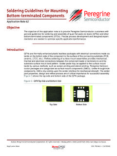
Soldering Guidelines for Mounting Bottom-terminated …
www.psemi.comThe solder paste is the vehicle that provides the flux and solder alloy necessary for a reliable and consistent assembly process. A low residue, no-clean solder paste (eutectic Sn63/Pb37 or lead-free SAC305/405 alloy SnAgCu) is commonly used. A water-soluble paste can be used if the residue can be adequately cleaned from underneath the package.

MSL Ratings and Reflow Profiles (Rev. A) - TI.com
www.ti.com• Liquidous temperature (TL) for lead-free soldering - this is approximately 217°C. This varies according to the used solder alloy. • The Peak temperature (Tp) for the reflow profile, measured at top of the package. – For the user (board assembly process), Tp must not exceed Tc as shown in Table 2. For the IC

Soldering - University of Technology Sydney
www.uts.edu.auTin/lead solder is still available and is used by “hobbyists” and other non-commercial users as it is still easier to use than lead free types. When using tin/lead (or leaded) solder there are additional safety precautions that must be observed. Different gauges of solder wire Solder composition is labelled (Lead free on left) Figure 3 ...