SOLID MECHANICS TUTORIAL – GEAR SYSTEMS
direction of rotation. It has no affect on the gear ratio. The teeth on the gears must all be the same size so if gear A advances one tooth, so does B and C. t = number of teeth on the gear. D = Pitch circle diameter. m = modem = D/t and this must be the same for all gears otherwise they would not mesh. m = DA/tA = DB/tB = DC/tC DA = m tA DB ...
Download SOLID MECHANICS TUTORIAL – GEAR SYSTEMS

Information
Domain:
Source:
Link to this page:
Documents from same domain

UNIT 22: PROGRAMMABLE LOGIC CONTROLLERS …
www.freestudy.co.ukD.J.DUNN 1 UNIT 22: PROGRAMMABLE LOGIC CONTROLLERS Unit code: A/601/1625 QCF level: 4 Credit value: 15 TUTORIAL – OUTCOME 2 Part 2 This work covers part of outcome 2 of the Edexcel standard module.

UNIT 22: PROGRAMMABLE LOGIC CONTROLLERS …
www.freestudy.co.ukD.J.DUNN 2 1. INTRODUCTION Programming a PLC is helped by various aids such as LOGIC CIRCUITS, LADDER DIAGRAMS, TRUTH TABLES and …

INTRODUCTION TO BEAMS - FREE STUDY
www.freestudy.co.uk© D.J.DUNN freestudy.co.uk 2 1 TYPES OF BEAMS A beam is a structure, which is loaded transversely (sideways). The loads may be …

EDEXCEL NATIONAL CERTIFICATE/DIPLOMA …
www.freestudy.co.uk© d.j.dunn www.freestudy.co.uk 1 edexcel national certificate/diploma further mechanical principles and applications unit 11 - nqf level 3 outcome 3 - rotating systems

EDEXCEL NATIONAL CERTIFICATE UNIT 10: …
www.freestudy.co.uk© d.j.dunn www.freestudy.co.uk 1 edexcel national certificate unit 10: properties and applications of engineering materials nqf level 3 outcome 1 - tutorial 1

INSTRUMENTATION AND CONTROL TUTORIAL 2 - …
www.freestudy.co.ukINSTRUMENTATION AND CONTROL TUTORIAL 2 – ELECTRIC ACTUATORS This is a stand alone tutorial on electric motors and actuators. The tutorial is of interest to

UNIT 61: ENGINEERING THERMODYNAMICS - FREE …
www.freestudy.co.uk© D.J.Dunn www.freestudy.co.uk 1 UNIT 61: ENGINEERING THERMODYNAMICS Unit code: D/601/1410 QCF level: 5 Credit value: 15 OUTCOME 4 STEAM AND GAS TURBINE POWER PLANT

Unit 24: Applications of Pneumatics and Hydraulics
www.freestudy.co.uk© D.J.DUNN 2 DIRECTIONAL VALVES 1. INTRODUCTION Valves are necessary to control the pressure, flow rate and direction of the fluid. Hydraulic valves are made

DYNAMICS TUTORIAL DAMPED VIBRATIONS Exam …
www.freestudy.co.ukSOLID MECHANICS DYNAMICS TUTORIAL – DAMPED VIBRATIONS This work covers elements of the syllabus for the Engineering Council Exam D225 – Dynamics of Mechanical Systems, C105 Mechanical and

SOLID MECHANICS DYNAMICS TUTORIAL …
www.freestudy.co.uk1.2 FREE VIBRATIONS- EXAMPLES A free vibration is one that occurs naturally with no energy being added to the vibrating system. The vibration is started by some input of energy but the vibrations die away with time as the energy
Related documents
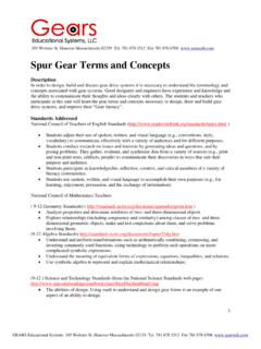
Spur Gear Terms and Concepts - Gears Educational Systems
www.gearseds.comThe pitch circle is the geometrical starting point for designing gears and gear trains. Gear trains refer to systems of two or more meshing gears. The pitch circle is an imaginary circle that contacts the pitch circle of any other gear with which it is in mesh. See fig. 6.3.1.5 below. The pitch circle centers are used to ensure accurate

DIAMETRAL PITCH SPUR GEARS - Custom Gear Products
commercialgear.comDIAMETRAL PITCH SPUR GEARS TO GET HAVING RULE FORMULA Module Diametral pitch Divide 25.4 by the diametral pitch m = 25.4 / Pd Module Divide 25.4 by the module Pd = 25.4 / m Circular pitch Divide π by the circular pitch Pd = π / P Pitch diameter and number of teeth Divided the number of teeth by pitch diameter Pd = N / D Outside of gear
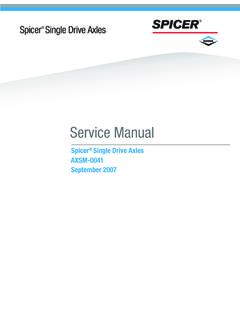
Service Manual - Spicer Parts
media.spicerparts.comRing Gear and Pinion Note: Ring gear and drive pinion are matched parts and must be replaced in sets. 1 - Part number 2 - Number of ring gear teeth 3 - Manufacturing numbers 4 - Matching gear set number 5 - Number of pinion teeth 6 - Date code 7 - Indicates genuine Spicer parts 8 - Heat code 1 S P 41-8 N O 1 1 8 1 P S 1 G 6-39 7 D J 50 4 8 EAT ...

GEAR MANUFACTURING PROCESS - 123eng
www.123eng.comHobbing is the process of generating gear teeth by means of a rotating cutter called a hob. It is a continues indexing process in which both the cutting fool & work piece rotate in a constant relationship while the hob is being fed into work. For in route gears, the hob has essentially straight sides at a given pressure angle. The hob
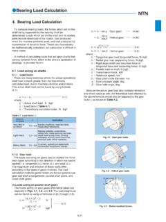
Bearing Load Calculation
old.ycbearing.comTable 4.3 Loads acting on bevel gears Gear type Ordinary machined gears (Pitch and tooth profile errors of less than 0.1 mm) Precision ground gears (Pitch and tooth profile errors of less than 0.02 mm) 1.05~1.1 1.1~1.3 f z Table 4.2 Gear factor f z For spiral bevel gears, the direction of the load varies

Tolerancing in ISO
users.encs.concordia.caMeasuring thread pitch • Pitch is the distance parallel to axis between corresponding points in adjacent thread • Pitch is measured in millimeters for metric thread and indicated along with the major dia (eg. M10 X 1.5) • For inch threads, it is mentioned as threads per inch • Thread Pitch is measured with scale or a thread pitch gage

Gears and Gear Ratios
www.clevehill.orgThe pitch of a gear is the distance between any point on one tooth and the same point ... First work on Gears Aand B. When this has been solved work on gears Band C. The diagram shows a gear train composed of three gears. Gear A revolves at 60 revs/min in a clockwise direction. What is the output in revolutions per

Gear Inspection and Measurement
www.geartechnology.commethod, the master gear and work: gear are mounted on fixed center distance with back-lash. (See Fig. 10.) The master gear drives the work gear. The relative angular rotation of the master and the work are compared and charted. This method can find the same errors as the dual flank: method and can al 0 detect angular velocity errors. Ana]ytica ...

chapter 1 INTRODUCTION TO DRIVETRAINS
www.pearsonhighered.comPITCH DIAMETER PITCH DIAMETER OF DRIVING GEAR PITCH DIAMETER OF DRIVING GEAR POINT A POINT B POINT C FIGURE 1–6 The pitch diameter is the effective diameter of the gear. Note how the contact points slide on the gear teeth as they move in and out of contact. GEARS TERMINOLOGY The effective diameter of a gear is the pitch diameter (or pitch line).