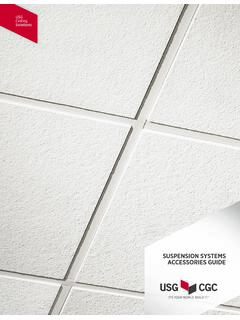
SUSPENSION SYSTEMS ACCESSORIES GUIDE
JB14 3/4" Radius 90° Outside Corner Cap for 7/8" Molding 100 3.0 JB16 3/4" Radius 90° Outside Corner Cap for 1" Molding 100 3.0 JM16 Field-Modified Corner for 1" Molding 100 3.0 INSIDE CORNERS A2 Inside Corner Cap for 7/8" Molding 200 4.0 A174 Inside Corner Cap for MS174 Shadow Molding 50 1.5 A274 Inside Corner Cap for MS274 Shadow Molding 50 1.5
Download SUSPENSION SYSTEMS ACCESSORIES GUIDE

Information
Domain:
Source:
Link to this page:
Documents from same domain

USG Fire-Resistant Assemblies Catalog (English) - …
www.usg.com4 USG Fire-Resistant Assemblies Fire Protection USG is the undisputed leader among building material manufacturers in providing products and systems designed to keep people safe from fire.

USG Area Separation Wall Systems Brochure …
www.usg.comArea separation walls between adjoining townhouses must provide fire-resistive ratings to ensure the safety of occupants in adjacent dwellings.

Fire-Resistant Assemblies Brochure (English) - SA100
www.usg.comUser’s Guide Use this brochure to determine fire ratings for CGC products and systems. This brochure provides: — Comprehensive information about fire-rated assemblies
Technical Document Seismic Technical Guide - USG
www.usg.com4 Hanger Wire Attachment Application Anchorage The International Building Code (IBC), through references to ASCE/SEI 7 Minimum Design Loads for Buildings and Other Structures, American Society of Civil Engineers/Structural Engineering Institute (ASCE/SEI), defines
Technical Document Seismic Technical Guide - USG
www.usg.comTechnical Seismic Technical Guide Document Light Duty Suspension Systems ASTM C6351 addresses the load carrying capability of main tees, categorizing them as Light, Intermediate or Heavy Duty.
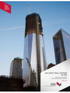
CGC SHAFT WALL SYSTEMS - USG
www.usg.comC-H studs in a progressive manner, with gypsum panels, gypsum fiber panels or cement board applied to the face. All details, specifications and data contained in this literature are intended as a …
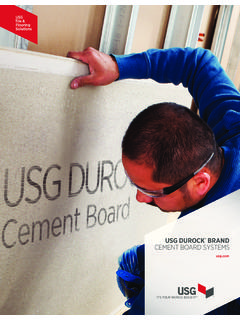
USG DUROCK BRAND CEMENT BOARD SYSTEMS
www.usg.comSTANDARDS USG Durock® cement board exceeds ANSI standards for cementitious backer units (CBU). See ANSI A118.9 for test See ANSI A118.9 for test methods and specifications for CBU and ANSI A108.11 for interior installation of CBU.
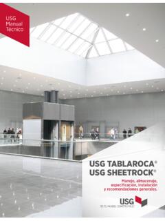
Manual Técnico USG Tablaroca® (Español)
www.usg.comUSG Manual Técnico USG TABLAROCA® USG SHEETROCK® Manejo, almacenaje, especificación, instalación y recomendaciones generales.
0 ICC-ES Evaluation Report ESR-1222 - USG
www.usg.comThe USG suspended ceiling framing systems described in this report are suspended, exposed framing, concealed ceiling assemblies used in fire-rated and non -resistance -
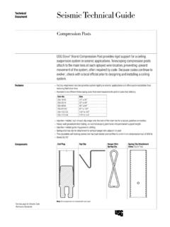
Technical Document Seismic Technical Guide - USG
www.usg.comTechnical Seismic Technical Guide Document Compression Posts USG Donn® Brand Compression Post providesidrig support for a ceiling suspension system in seismic applications. Telescoping compression posts attach to the main tees at each splayed wire location, preventing upward
Related documents
Injection Molding - MIT
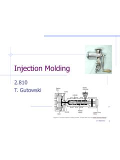
web.mit.eduSimilar to an injection molding machine, but without a mold and continuous production. Thus it has a similar energy consumption profile. Environmentally Unfriendly Additives: •Fluorinated blowing agents (GHG’s) •Phalates (some toxic to human liver, kidney and testicles) •Organotin stabilizers (toxic and damage marine wildlife) 47
Part and Mold Design - MTN
www.mtn.com.tr125 Molding Undercuts 128 Part Ejection 130 Mold Venting 130 Parting-Line Vents 131 Vent Placement 133 Sprues, Runners, and Gates 133 Sprues 134 Runners 137 Runners for Multicavity Molds 140 Gates 144 Other Gate Designs 145 Gate Optimization 147 Gate Position 149 Hot-Runner Systems 149 Hot-Runner Designs 149 Hot-Runner Gates 151 Valve Gates

Plastics Processing - University of Rhode Island
personal.egr.uri.eduStructural Foam Molding • A variation of the injection molding process, developed for applications where stiffness is a primary concern, and particularly for large structural parts. • Parts consist of a rigid, closed-cellular core surrounded by a continuous, solid skin. • The polymer melt contains a dissolved inert gas; most

% b.o. ISO 2577 0.5 - 0.7 C Molding shrinkage, normal ...
solutions.covestro.cominjection molding - melt temperature 280 - 320 °C; available in transparent, translucent and opaque colors ISO Shortname PC Property Test Condition Unit Standard typical Value-Rheological properties C Melt volume-flow rate 300 °C/ 1.2 kg cm³/10 min ISO 1133 19 Melt mass-flow rate 300 °C/ 1.2 kg g/10 min ISO 1133 20
Pneumatic and Hydraulic Drawing Information
www.eng.auburn.eduPlastics & Injection Molding Food Processing Forestry & Lumber Material Handling Packaging Recycling / Waste Management Rail & Trucking. Pneumatic Schematic Generation Methods Computer Aided Method HyPneu Fluid Power Software Company: BarDyne, Inc. Pros: Comprehensive Symbol Library that Meets ISO

INJECTION MOLDING PROCESSING GUIDE - Lubrizol
www.lubrizol.comLubrizol’s portfolio of injection molding grades includes ... injection pressure minimizes the possibility of producing highly stressed parts. This is significant because many new thermoplastic polyurethane molded parts are painted, and paint systems require baking for 30 …
Injection Molding - Pennsylvania State University
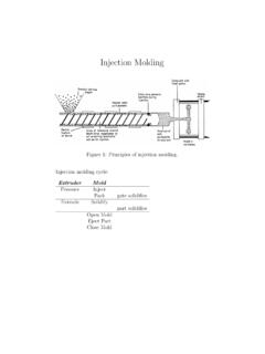
zeus.plmsc.psu.eduInjection Molding SIZING AN INJECTION MOLDING MACHINE Packing pressure ∼= 108Pa Clamping force F = P∗A Figure 7: Clamping force as a function of surface area. Note: logarithmic scales. Mold a single tensile bar - 50 ton machine Mold a front end of a car - 5000 ton machine “Typical” sizes are 100-1000 tons For complicated parts A ...