
The basic logic gates arethe inverter (or NOT gate), the ...
multiplexers) and any function that can be expressed in Boolean expression form. One key characteristic of combinational logic is that outputs completely determined by the input values at a given time. As soon as input changes, soon afterwards, the output will change if necessary. Since the logic gates themselves have delay,
Download The basic logic gates arethe inverter (or NOT gate), the ...
Information
Domain:
Source:
Link to this page:
Documents from same domain

6: Operational Amplifiers
www.ee.ic.ac.uk6: Operational Amplifiers 6: Operational Amplifiers •Operational Amplifier •Negative Feedback •Analysing op-amp circuits •Non-inverting amplifier •Voltage Follower

FINANCIAL REGULATIONS PREAMBLE
www.ee.ic.ac.uk1 FINANCIAL REGULATIONS PREAMBLE 1.1 These Regulations are made by the Director of Finance, acting on the advice of the Management Board, under powers conferred by the Council under paragraph 5 of Ordinance C1.
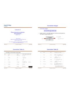
Convolution Table (1) Convolution Table (2)
www.ee.ic.ac.ukwith System’s impulse response h(t). Convolution Integral ... weighted by h(t- τ) (i.e. x(τ) h(t- τ)) for the shaded pulse, PLUS the contribution from all the previous pulses of x(τ). The summation of all these weighted inputs is the convolution integral. L2.4-2 p191
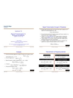
Signal Transmission through LTI Systems
www.ee.ic.ac.ukPYKC 20-Feb-11 E2.5 Signals & Linear Systems Lecture 12 Slide 9 Parseval’s Theorem The energy of a signal x(t) can be derived in time or frequency domain:
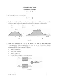
Tutorial 7 - Sampling
www.ee.ic.ac.ukPYKC – 11 Feb 08 2 E2.5 Signals & Linear Systems Tutorial Sheet 7 – Sampling (Lectures 12 - 13) 1.* By applying the Parseval’s theorem, show that

Lecture 8 - Timing Constraints
www.ee.ic.ac.ukMetastability is a problem that arises when an external input NOT synchronised to the system clock is fed into our synchronous circuit. Since the input signal could change anytime relative the the clock edge, metastability will occur. It could also happens when a signal crosses from one clock domain (Clock1) to another clock domain (Clock2).

14: Power in AC Circuits
www.ee.ic.ac.ukCosine Wave RMS 14: Power in AC Circuits •Average Power •Cosine Wave RMS •Power Factor + •Complex Power •Power in R, L, C •Tellegen’s Theorem •Power Factor Correction •Ideal Transformer •Transformer Applications •Summary E1.1 Analysis of Circuits (2017-10213) AC Power: 14 – 3 / 11 Cosine Wave: v(t) = 5cosωt.Amplitude is V = 5V. Squared Voltage: v2(t) = …

SERVO MOTOR SG90 DATA SHEET - Imperial College London
www.ee.ic.ac.ukSERVO MOTOR SG90 DATA SHEET Tiny and lightweight with high output power. Servo can rotate approximately 180 degrees (90 in each direction), and works just like the standard kinds but smaller. You can use any servo code, hardware or library to control these servos.

17: Transmission Lines
www.ee.ic.ac.uk• Forward Wave • Forward ... A transmission line is a wire with a uniform goemetry along its length: the capacitance and inductance of any segment is proportional to its length. We represent as a large number of small inductors and capacitors spaced along the line.

8: Correlation - Imperial College London
www.ee.ic.ac.ukE1.10 Fourier Series and Transforms (2015-5585) Fourier Transform - Correlation: 8 – 3 / 11 Cross correlation is used to find where two signals match: u(t) is the test waveform.
Related documents

Lecture 2 – Combinational Circuits and Verilog
courses.cs.washington.eduLarge multiplexers can be implemented by cascading smaller ones using a tree structure . 27 A B C 0 A'B'C' 1 A'B'C 2 A'BC' 3 A'BC 4 AB'C' 5 AB'C 6 …
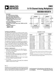
a 8-/16-Channel Analog Multiplexers CMOS …
www.analog.commultiplexers with 16 channels and dual 8 channels, respectively. The ADG506A switches one of 16 inputs to a common output, depending on the state of four binary addresses and an enable input. The ADG507A switches one of eight differential inputs to a common differential output, depending on the state of three binary addresses and an enable input.
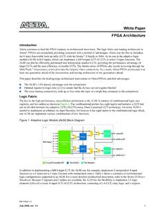
FPGA Architecture White Paper - Intel
www.intel.comSRAM bits to hold the configuration memory (CRAM) LUT-mask and a set of multiplexers to select the bit of CRAM that is to drive the output. To implement a k-input LUT (k-LUT)—a LUT that can implement any function of k inputs—2k SRAM bits and a 2k:1 multiplexer are needed. Figure 2 shows a 4-LUT, which consists of 16 bits of

Experiment # 7 Multiplexers And Demultiplexers
site.iugaza.edu.psMultiplexers: In electronics, a multiplexer (or mux) is a device that selects one of several analog or digital input signals and forwards the selected input into a single line. A multiplexer of 2n inputs has n select lines, which are used to select which input line

Optical Networks – Basic Concepts (Part 1)
www.iitg.ac.inAdddrop multiplexers using optical devices are called Optical Add/drop Multiplexers (OADM). Figure 10: An optical adddrop multiplexer (OADM) Optical Devices/components End nodes : sources or destinations of data (typically computers) . Optical routers : direct each incoming optical signal to an

AN5306 Introduction Application note - STMicroelectronics
www.st.comdefined using a set of analog multiplexers which interconnect the OPAMP input and output terminals through an internal resistor network. Final gain of this programmable gain amplifier (PGA) is defined by the resistor ratios on the feedback. Figure 3. Internal OPAMP connections in STM32G4 Series illustrates the basic schematic of the OPAMP
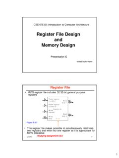
Register File Design and Memory Design
web.cse.ohio-state.eduThis is the RF design at the level of registers and multiplexers. Read regis ter numbe r 1 Read data 1 Read data 2 Read register number 2 Register file Write regi ster Write data Write 5 5 32 32 M u x R egi t r0 R gist r1 Registern–1 Registern M u x Re ad t 1 Re ad t 2 Readregister number1 R ead rgst number2 n=31 Figure B.8.8
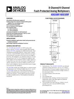
8-Channel/4-Channel Fault-Protected Analog Multiplexers ...
www.analog.commultiplexers provide fault protection. Using a series n-channel, p-channel, n-channel MOSFET structure, both device and signal source protection is provided in the event of an overvoltage or power loss. The multiplexer can withstand continuous overvolt-age inputs from −40 V to +55 V. During fault conditions with