
The Gear Hobbing Process
the number of threads ill the hob. '. A means of traversing the curnag too! across the face of the work in the direction of the work axis for spur and helical gears. • A means of adjusting the center distance of the work and the hobs for different size workpieces, Figs. 8-W show schematics for three typical bobbing machines. Hobbing Feed
Download The Gear Hobbing Process

Information
Domain:
Source:
Link to this page:
Documents from same domain

High-Temperature Testing of Stanyl Plastic Gears: A ...
www.geartechnology.comGenerate high-temperature fatigue data for various Stanyl tensile bars at the same temper- ature. 3. Incorporate the influence of tooth bending on the root ... Tensile bar fatigue testing. The tensile bar fatigue tests were run on standard ISO 527-1A injection molded specimens. The specimens were sub-

Product News - March/April 2018 Gear Technology
www.geartechnology.comMitutoyo America Corporation RELEASES MICAT PLANNER VERSION 1.5 Mitutoyo America Corporation recently announced the release of MiCAT Planner v1.5 for the company’s coordinate measur-ing machines. In as little as one click, MiCAT Planner auto-mates the generation of measurement programs based on CAD

Don’t Get Burned - Gear Technology
www.geartechnology.comfeature DON’T GET BURNED. late. You have to have your own lab, and customers need to make sure they’re going to a heat treat with a lab and an experienced staff who knows how to use it. This could save several days. Q: What specifications and/or certifications do you
New ANSI/AGMA Accuracy Standards for Gears
www.geartechnology.comupon local standards, such as AGMA, DIN, JIS, BGA, etc., to internation- al adoption of ISO standards, which are now positioned to become the default specifications for global commerce in gear products.
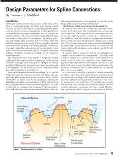
Design Parameters for Spline Connections
www.geartechnology.comIf the splines are being designed, then one of the preferred pres-sure angles from the standards should be used. ANSI and DIN offer the choice between 30°, 37.5° and 45°. In the JIS standard also a pressure angle of 20° is proposed. If the spline is designed for an aftermarket product (for example the sprocket shown Fig. 7), then a simple ...

Back to Basics - Gear Design
www.geartechnology.comBACK TO BASICS. • ... mission are inversely proportional to' the numbers ,of teeth (not the pitch diameters) in the gears mounted on the shafts. With the relative speed of one member of a pair of gears known, the speed of the mating gear is easily obtained by the equation:

Gear Inspection and Measurement
www.geartechnology.commethod, the master gear and work: gear are mounted on fixed center distance with back-lash. (See Fig. 10.) The master gear drives the work gear. The relative angular rotation of the master and the work are compared and charted. This method can find the same errors as the dual flank: method and can al 0 detect angular velocity errors. Ana]ytica ...

Involute Spline Size Inspection - Gear Technology
www.geartechnology.comthe intereoupling of motors with gear boxes or other loads. Since there is no l10lling action between the mating members. as there is between meshing gears. aU of the spline teeth are expected Ito fit together. AI.though various internal andexter:nal fits are available, the final goal of involute splines isto achieve a self centering con-

Gear Hardness Technology
www.geartechnology.combetween AfSI 4140, a leanalloy steel withpoor hardenability, and AI;S~4340. a rich alloy steel. In order to compare the hardenability of a material. end quench (Jominy) values are widely used as an indicator of a steel's hardenability, Since the quench is so critical to the resulting microstructure, it is necessary to verify the results with an ...

A Comparison of Current AGMA, ISO and ... - Gear Technology
www.geartechnology.comgrally geared centrifugal compres-sors did not exist at that time. The 2002 seventh edition expanded the scope to cover Integrally Geared Centrifugal Compressors and Expander-compressors. It is now essentially three standards pack-aged as one. Each section has its own set of annexes, and for integrally geared cen-
Related documents

Guidelines for U-Bolt Design - Clamps, Inc
www.clampsinc.comJul 27, 2015 · involved. The threads are much harder, due to the tremendous cold working they undergo during rolling, than the rest of the bolt. Because of the thread geometry, a hardness test is not practical in the threads themselves and a tensile test is a better indication of overall bolt strength. The additional hardness of the threads provides
THREAD CUTTING & FORMING - Concordia University
users.encs.concordia.caTapping: Machining Threads on Internal Diameters (holes) Size: Watch to 10” shafts Straight Threads: Threads on cylindrical surfaces, ex. fasteners Conical Threads: Threads on conical surfaces, ex. Pipe joints Methods: Thread Rolling-small and standard parts, …

Differentials and Drive Axles Study Notes
cf.linnbenton.eduDifferentials and Drive Axles Study Notes Purposes of a Drive Axle Assembly • To transmit power from the drive shaft to the wheels • To turn the power flow 90-degrees on RWD cars • To allow the wheels to turn at different speeds while cornering RWD Live Axle Components • Rear axle housing – Holds all other components and attaches to the vehicle’s suspension

TYPES OF GRINDING WHEELS
www.rajagiritech.ac.inthreads an gear teeth. Type 5. It is used for surface grinding, i.e. production of flat surfaces. ... moulded by rolling and pressing and then by heating upto 150°C for several hours. This bond exhibit greater ... The only satisfactory method of truing a wheel is by the use of a diamond tool in a similar manner as explained before. In turning a