Transcription of The Gear Hobbing Process
1 :38 GEARTECHNO~OGYThe Gear HobbingProcessDennis ,GimpertK'oepfer America Limited Partnership"South Hobbing is a generating proces .The termgeneratingrefers to the factthat the gear tooth form cut is lIotlllcconjugate form of the cutting tool,lhehob. During Hobbing both the hob and theworkpiece rotateilla continuous [)uringthis rotation, the hobitypically fed axiaUywithallthe teeth beinggradually formed as the tool traverses the workface (see ).FOIl"a spur gear being cut with a single starthob, the workpiece will advance one tooth foreach revolution of the cutter. Wilen bobbing atwenty-tooth gear" the hob will rotate twentytimes, while the workpiece will rotate profile is formedbythe equally spacedcutting edgesaroundthehob, each taking sue-cessive cuts on the workpiece, with the work-piece ,in a slightly different po ition for eachcut (see Fig.]
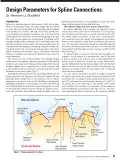
2 Ib). Several cutting edge of thetool will be cutting at the arne hobisbasically a wonn with acrossitto produce these cuttingedges. Each cutting tooth is also relievedradiallytoprovide chip clearance behind thecutting edge. This also allowsthe hob face tobe sharpenedandstill maintain the originaltooth shape. The final profile of the toothjcreatedbya number of flats blending togeth-er. The number of flats correspondsto thenumber of cutting gashes which pass theworkpiecetoothduring a single , the greater the number of gashes in thehob, thegreater the number of flats along :~.15J"DP"Fine Pitch isLengthActive Length- ---Filg. 2profile which improves the "smoothness"ofthe tooth CutterBobbing is a generating Process , and thehob win not cut the same shape as the cuttingtool form, An unmodified involute gear toothis producedby.
3 <11hobwithstraight-sided cut-ting edges. Involete gear cutting is the largestapplication of bobbing (Fig. 2). In contrast, astraight-sided spline toothisproducedby ahobwith curved cutting edges (see Fig. 3).Cutter ModificationsIt is possible to design the shape of a cuttingtool to produce modified tooth forms. Theseare done for various reasons. The hob toothroot canbedesigned to cut the outside diame-ter of the gear tooth. With this "topping" hob,the tooth involute and the outside diameter ofthe blank will be hobbed in one operation ( ). This may eliminate finish turning of thegear blank, reducing machine outside diameter of the gear will beconcentric with the operating pitch diameter ofthe gear.
4 This win provide a locating surfaceforsubsequent operations andamethod ofmea uring corners between the tooth flank: andoutside diameter can be eliminatedwith a"semi-topping"or "tip chamfering" hob (seeFig. 5). With proper design such a hob mayalso correct the problem of gear tooth bendingunder load,Gears which willbe finished byasubse-quent operation, such as skiving, shaving orgrinding, may require clearance in the geartooth fillet area for the finishing tool. This canbe cut using a "protuberance" hob. which Depthof ToolhFig. 5 DennisG,imp'eirtis rilepreidem ofKoepferAmuletlLimitedPartnershipillSou thElgin, IL. He is theauthor of several articlesongearing 'Paint ofIntersectionofPre-ShavedProlilawlthUnd ercutLowest Point01 " with MatingGear~Greater ~\ ,than-Shaving Stock(Dependsupon DiarnetralPitch)Root Fillet Worm Gear ( )DifferentialChange GearsSpeed Change Gears---Fig.
5 8 Mechanical Vertical Hobblng \TECHNOLOGY produce undercut (see Fig. 6).. The protuber-ance hob is designedtoprovide a uniformstock for the finishing tool and to provide ablendbetween the bobbed root area and thefinished flank. Caution: On any modified cut-ter, we are changing the correct rack , the tool may cutonlya certain rangeofgear teeth numbers correctly ( ).The Gear Hobbingl MachineAgear bobbillg machine consistsoffivecommon elements: Awork spindletorotate the work. Ahob spindletorotate the the work spindle andhob spindle with a constant of ratio, dependingon the number of teeth in the workpieceamithe number of threadsillthe hob.'. Ameans of traversingthecurnag too!
6 Across the face of the work in the direction ofthe work axis for spur and helical gears. Ameans of adjusting the center distanceof the work and the hobs for different sizeworkpieces, Figs. 8-Wshow schematics forthree typical bobbing FeedDuring bobbing, the cutting tool can be fedina manner similarto'a milling machine; bothconventional and climb bobbing are used ( ). Ageneral rule of thumb is thatclimbhobbing yields better tool life,and! convention-al Hobbing yields a betterfinish, ,the cutting force should be directed againstthework spindle, never against the directionsof feed on a hobbingmachine correspondtothe work axis .. Thus,three feeds are possible - axial, radial andtangential (Figs.)
7 12a, b, c).It is also possible to combine more than oneaxis of feed sequentiallyorsimultaneouslyduring the machinecycle,A radial feedapproach followedby axial feed across theface is very typi:calin fine pitch gear work oronaworkpiece where an open axialapproachis not possible (Fig. 13).Axial and tangenti,ai feed are used imulta-neously for several purposes on very large,coarse pitch, wide-faced gears. The tangentialfeed portionofthe tool as theaxial feed cuts across the gear face (Fig .. 14).Taper rootsplinesarecutwith simultaneousaxial and tangenti .alfeed (Fig. I5).A "jump" or "skip" cycle is used. to cutrnul-Radial, FeedDriveMotorAxial FeedConventionalClimb FeedConventional Feedl~-:tFig.
8 Used for Worm FeedRadial Feed Approach with Axiall FeedJANUARY/FEBRUARYA xial and Tangential Feed--Fig. 14 Taper Root HobTaper Root CycleTapered GearCrowned Gear42 Fig. 11 GEARTECHNOLOGYtip le gear elements a single part. This maybe required for gear tooth alignment or simplecutting efficiency (See Fig. 16).Tapered gears or crowned gears are pro-duced with simultaneous radial and axial feed(Fig. 17).At the beginning of the Hobbing machinecycle, the cutter will not. be generating the fulldepth of the gear tooth form. Only a small cutis made by each tooth in the hob graduallyfeeding into the part. Thisisknown asthe"approach" portion of the hobbi ng cycle.
9 It ispossibleto utilize adifferent feed rate duringthisapproaehIength with a reductionincycletime ( ).During thehobbingofsome gearsorsplines, the cutter win not feed completelythrough the workpiece face ..This is known as a"blind" cut. To complete all of the teeth evenlyaround the circumference of the gear, "dwell"is utilized. During dwell the hob and work-piece continue to rotateilla timed relationshipfor oneortwo more work revolutions,hutwithout feed (Fig. 19).Multilple,Start HollsThe hob is a series of racks positionedaround the circumference of a cylindrical successiverackis shifted axially to createa worm, typically a single thread . Thus, foreach revolution of a single start hob, thegearmust advance one tooth space (see Fig.)
10 20).This is accomplishedbythe bobbing machinekinematic indexing ,itis important to understandwhat causes the cuttingmarkson a hob axially across the face oftinegearwiH carre pond directly withtheaxialfeed per work: revolutionof the tool. Themarks positioned across the profile of the directly with the number ofgashes or flutes on the hob (Fig. 2 O. Normallyitis notpossible to see the generating flatsalongtheprofileof is possible to increase the speed of thehobbing operationbyutilizinga hob with morethan one example,ifthe hob hastwothreads, the gear must advancetwotoothspaces for each revolution of that double the speed of the work and factors being equal(Fig.)