Transformer Manufacturing Processes
Transformer Consulting Services Inc. Winding Selection Manufacturing Process: Based on: •winding voltages: (nominal, test, impulse, …) –number of turns –electrical clearances –ZnO discs allowed? •winding current: –needed Copper cross-sectional area –maximum allowed temperature (average and hottest spot)
Download Transformer Manufacturing Processes

Information
Domain:
Source:
Link to this page:
Documents from same domain
Low Drop-Out (LDO) Linear Regulators: Design ...
site.ieee.org1 IEEE Santa Clara Valley (SCV) Solid State Circuits Society February 11, 2110 Edgar Sánchez-Sinencio TI J. Kilby Chair Professor Analog and Mixed-Signal Center,
Transformer Protection Application Guide
site.ieee.orgTransformer Protection Application Guide This guide focuses primarily on application of protective relays for the protection of power transformers, with an emphasis on the most prevalent protection schemes and transformers. Principles are emphasized. Setting procedures are only discussed in a general nature in the material to follow. Refer to ...
Power System Protective Relays: Principles & Practices
site.ieee.orgIEEE Std C37.102-2006 IEEE Guide for AC Generator Protection IEEE Std C37.106-2003 IEEE Guide for Abnormal Frequency Protection for Power Generating Plants IEEE Std C37.108-2002 (R2007) IEEE Guide for the Protection of Network Transformers IEEE Std C37.109-2006 IEEE Guide for the Protection of Shunt Reactors
PREPARATION OF TRANSFORMER SPECIFICATIONS
site.ieee.orgWhen an old single-phase transformer fails, it is often replaced with a new single-phase transformer. For a functionally identical new transformer, losses, weight and dimensions are often much lower than those of the old transformer. This is due to improvements in materials, accurate design analysis with advanced mathematics, computers and better

Transformer Installation, Assembly & Testing
site.ieee.orgprocess and test the transformer are of fundamental importance to the long life of the transformer. •The installation and testing of the transformer verifies its condition at the time it is ready for service as well as forming the baseline or signature tests for all future maintenance and later condition assessment or analysis.

Partial Discharges in Electrical Insulation
site.ieee.orgPD Testing of Power Cables •For oil-paper transmission class, primarily use on - line PD •All XLPE and EPR cables: all factory PD tested •In-situ off-line PD testing: use 50/60 Hz or VLF (0.1 Hz) to energize the power cable capacitance •On-line PD testing of cables sometimes also performed – but high risk of false indications due to

Understanding MV Cables Testing, applications, cable ...
site.ieee.orgMining Cables • Built to 2 different CSA Standards –C68.10 and C22.2 #131 • In Canada most 5KV historically has been 3c unshielded Teck90 • In the US the NEC requires 5KV cables to be shielded • Shield drains any leakage currently safely to ground

Introduction to Partial Discharge (Causes, Effects, and ...
site.ieee.org•Influenced by environment (e.g. temperature, humidity, pollution). •When monitoring ultrasonically the environmental conditions (%RH and Temperature) should also be monitored •Discharge has a distinctive crackling noise. •Often intermittent, particularly during early stages.
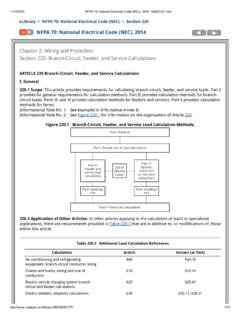
NFPA 70: National Electrical Code (NEC), 2014 Chapter 2 ...
site.ieee.orgIndustrial machinery, supply conductor sizing 670 670.4(A) Marinas and boatyards, feeder and service load calculations ... spaces not adaptable for future use. ... the lighting load exceeds the values set by the energy code.
IEEE Power & Energy Society TECHNICAL REPORT Jan 2013 …
site.ieee.orgmodrn gas turbines),this can have some affet on transient ste c abiliy and it should t. be modeled accordingly. The modeling of the turbine‐governor is of greatest importance when studying frequency control and stability. Frequency response is …
Related documents

EE 340 Spring 2011 - UNLV
www.egr.unlv.eduapplied to the rotor winding producing a rotor magnetic field. The rotor is then turned by external means producing a rotating magnetic field, which induces a 3-phase voltage within the stator winding. • Field windings are the windings producing the main magnetic field (rotor windings • armature windings are the windings
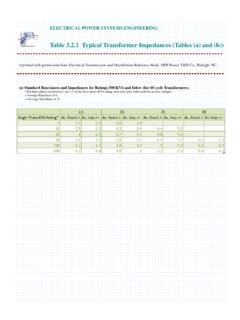
Table 3.2.1 Typical Transformer Impedances (Tables (a) and ...
community.ptc.comELECTRICAL POWER SYSTEMS ENGINEERING Table 3.2.1 Typical Transformer Impedances (Tables (a) and (b)) reprinted with permission from Electrical Transmission and Distribution Reference Book, ABB Power T&D Co., Raleigh, NC. (a) Standard Reactances and Impedances for Ratings 500 KVA and below (for 60 cycle Transformers).
Mn-Zn Ferrite Cores for Switching Power Supplies PQ ... - TDK
product.tdk.comThe PQ Core occupies a smaller mounted area, as a transformer, compared to the E-core and EER-Core APPLICATION Tranformers and coils for Switched-mode power supplies (High Mounting Density, Low Profile) PART NUMBER CONSTRUCTION RANGE OF USE AND STORAGE TEMPERATURE Overview of the PQ Series PC47 PQ20/16 Z - 2 2 Material Size of …
Lesson 9: Practical Transformer Model and Calculations
www.engr.siu.eduTransformer Voltage Drop and Impedance Lesson 9_et332b.pptx 18 Example 9-2: The equivalent resistance and reactance of a 50 kVA, 2400-480 V transformer's windings are R = 2.80 W and X = 6.00 W. (high side). A load of 10 20o is connected to the low voltage side. Determine: a) equivalent impedance of the transformer and load combined
Transformer asics Information Guide - Motion Labs
www.motionlabs.comA transformer that is fed, on the primary winding, by a single alternating voltage, which can be represented by a single sine wave. The secondary winding can be “split” or “tapped”, to produce multiple voltages, such as, 120/240V. If a transformer connection is rearranged from step up to step down or step down to
Section 4 – Power Transformer Design
www.ti.comthe transformer. R I from surface to internal hot spot is not relevant because very little heat is actually gener-ated at that point. Most of the heat generated in the core (other than in toroids) is near the transformer surface. Heat generated within the winding is distrib-uted from the surface to the internal core. Although
'Magnetics Design 5 - Inductor and Flyback Transformer …
www.ti.comnition). However, the current in each winding of any flyback transformer is always highly discontinuous, regardless of inductor current mode. This is because current ( ampere-turns ) transfers back and forth be-tween primary and secondary(s) at the switching fre-quency. As shown in Fig. 5-3, the current in each