
User Manual - Thrustmaster
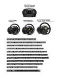
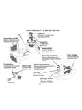
2/11 8 Pedal cable 9 RJ45 connector for pedal set 10 Table clamp 11 Clamp screw 12 USB connector (for PC and PlayStation®3) 13 Pedal set INSTALLING THE WHEEL Fixing the wheel in place 1. Place the wheel on a table or other flat surface. 2. Place the clamp screw in the table clamp (11) (10) and then screw the clamping unit into the hole on the underside of the wheel …
Download User Manual - Thrustmaster

Information
Domain:
Source:
Link to this page:
Documents from same domain
ITALI ANO - Thrustmaster
ts.thrustmaster.comENGLISH: Manual firmware update procedure (Windows 7 / 8 / 8.1 / 10) On PC, the USB sliding switch on the T300 racing wheel’s base must always be set to the PS3 position!
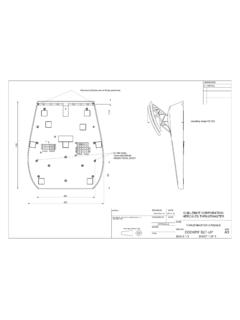
A3
ts.thrustmaster.com310 99 204 267 11,5 operating range125-220 drawn by date guillemot corporation hercules thrustmaster thrustmaster 2013-11-20 checked by date name approvals thrustmaster 2 …
HOTAS Warthog - Manual Firmware update …
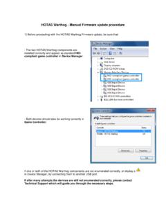
ts.thrustmaster.comHOTAS Warthog - Manual Firmware update procedure 1) Before proceeding with the HOTAS Warthog Firmware update, be sure that: - …
MANUEL DE L’UTILISATEUR - ts.thrustmaster.com
ts.thrustmaster.com2/44 – Manuel de l’utilisateur T.A.R.G.E.T v3.0 Avant-propos Bienvenue dans ce manuel et félicitations pour votre achat. Nous espérons que ce contrôleur de …
Need For Speed ™ - Wheel settings - Thrustmaster
ts.thrustmaster.comNeed For Speed ™ - Wheel settings These settings are necessary to your Thrustmaster wheel with: - Need For Speed ™ Most Wanted - …
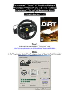
ColinMcRae Dirt Ferrari GT WHEEL - Thrustmaster
ts.thrustmaster.comThrustmaster™ “Ferrari™ GT 2‐in‐1 Rumble Force” Thrustmaster™ “Ferrari™ GT 2‐in‐1 Force Feedback” Thrustmaster™ “Ferrari™ GT Experience 3‐in‐1” “COLIN McRae Dirt™ ‐ PC” Step 1
FLIGHT SIMULATOR™ X - DEFAULT MAPPING
ts.thrustmaster.com2/4 FLIGHT SIMULATOR™ X - DEFAULT MAPPING Throttle (meer/minder) Alza flap (passo Subir alerones (paso a paso) Visuale panoramica Vista panorámica Roer links/rechts

ENGLISH - “RACING WHEEL MODE” AND “GAMEPAD MODE” …
ts.thrustmaster.comincrease the T80 Racing Wheel's sensitivity (for more information on this subject, please refer to the section below, “Adjusting the r acing wheel's sensitivity in “Gamepad Mode”). ADJUSTING THE RACING WHEEL'S SENSITIVITY IN “GAMEPAD MODE”
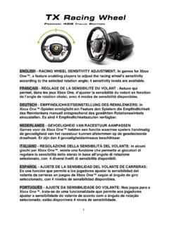
ENGLISH - RACING WHEEL SENSITIVITY ADJUSTMENT: In …
ts.thrustmaster.comThe racing wheel automatically reverts to Sensitivity level 1 (i.e. default mode) when the system restarts or the wheel is disconnected from the system. Manually adjusting the sensitivity level slightly alters the intensity of the racing wheel's
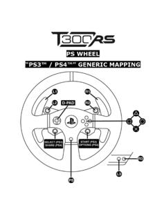
PS WHEEL - Thrustmaster
ts.thrustmaster.com1.2 a d-pad select (ps3) share (ps4) start (ps3) options (ps4) 1.3 aoo
Related documents
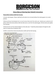
Chevy Manual Steering Gear Rebuild Instructions
www.borgeson.comChevy Manual Steering Gear Rebuild Instructions Disassembly of pitman shaft from housing: 1) Center steering gear. ... Corvette and 55-57 steering gears have two bushings in the housing. The rebuild kits for these gears will ... Installing Pitman shaft Into housing: 1) With an 1-1/8” socket tap the pitman shaft seal into position in the ...
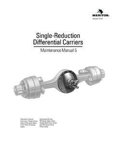
Single-Reduction Differential Carriers - Parts Manuals
partsmanuals.orgThis manual provides instructions for Meritor’s early production non-RF, -RS or -RT Series axles. Before you begin procedures: 1. Read and understand all instructions an procedures before you begin to service components. 2. Read and observe all Caution and Warning safety alerts that precede instructions or procedures you will perform.

PRE-RIDE CHECKLIST Bicycle Owner‘s Manual
www.cannondale.comsteering tube. Similarly, the seatpost must be secure in the seat tube (See PART I, Section 3. Fit). Are you visible to motorists? If you are riding at dusk, dawn or at night, you must make yourself visible to motorists. Use front and rear lights and a strobe or blinker. Reflectors alone do not provide adequate visibility. Wear reflective

PPlease read this manual and save it with your lease read ...
www.fisher-price.com• To prevent damaging the motors and gears, teach your ... 2 Rear Wheels Steering Post (Left and Right) 2 Front Wheels (Left and Right) Steering Column 2 Rims. 5 W2602pr-0920 ... Installation section for instructions on installing your battery. If …

391.41 CMV DRIVER MEDICATION FORM
www.fmcsa.dot.govto control an oversize steering wheel, shift gears using a manual transmission, and maneuver a vehicle in crowded areas. The above patient/driver is being evaluated to determine whether he/she meets the medical standards of the Federal Motor Carrier Safety Administration (FMCSA) to operate a commercial motor vehicle (CMV) in interstate commerce.

Owner‘s Manual
www.gtbicycles.comOther Manuals & Instructions Many of the components on your bike were not made by GT. When available from the manufacturer, GT packages these manuals and/or instructions with our bikes for delivery to you. We strongly recommend that you read and follow all the manufacturer’s specific instructions included with your bike. Authorized GT Dealers

1.0 1.0 INSTALLATION INSTRUCTIONS PERFORMANCE …
www.iequus.comOpening for Steering Column Mount Figure 1 3 TACHOMETER CONNECTIONS Power and Ground Connections (Figure 3) 1. Plug the 3-pin power connector (RED, BLACK and WHITE wires) into the #2 connector on back of the tachometer. 2. Connect the tachometer's power (RED) wire to a switched +12 volt circuit