WIND & SEISMIC - AWC
4.3 Wood-Frame Shear Walls 4.4 Wood Structural Panels Designed to Resist Combined Shear and Uplift ... nominal strength to an allowable stress design level. BOUNDARY ELEMENT. ... discontinuities, and re-entrant corners. CHORD. A boundary element perpendicular to the applied load that resists axial stresses due to the in-duced moment. COLLECTOR.
Download WIND & SEISMIC - AWC

Information
Domain:
Source:
Link to this page:
Documents from same domain

INTERIOR SHEAR WALLS - awc.org
www.awc.orginterior shear walls to be designed to resist wind loads. WFCM Section 2.4.4.2 states: “Walls parallel to the applicable wind load or seismic motion shall provide the required shear resistance at each level. The sum of the individual shearwall segment shear
2012 ASD/LRFD Manual for Engineered Wood Construction
www.awc.orgASD/LRFD MANUAL FOR ENGINEERED WOOD CONSTRUCTION iii AMERICAN WOOD COUNCIL FOREWORD This Allowable Stress Design/Load and Resistance Factor Design Manual for Engineered Wood Construction (ASD/LRFD Manual) provides guidance for design of most wood-based structural products used in the construction
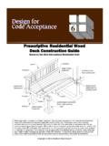
Prescriptive Residential Wood Deck Construction Guide
www.awc.org4 PRESCRIPTIVE RESIDENTIAL WOOD DECK CONSTRUCTION GUIDE American Wood Council Table 2. Maximum Joist Spans and Overhangs.1 Species Size Joist Spacing (o.c.)
2015 National Design Specification Supplement - awc.org
www.awc.orgAMERICAN WD CUNCIL. DESIGN VALUES FOR WOOD CONSTRUCTION – NDS SUPPLEMENT iii. Introduction. This Supplement is a compendium of reference de …
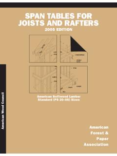
2005 Span Tables For Joists And Rafters - awc.org
www.awc.org2 EXPLANATION OF TABLES AMERICAN WOOD COUNCIL 7. LUMBER IDENTIFICATION The tabulated spans in these tables apply to lum-ber identified by the grade stamp of, or certificate of

Design Aid 6 Beam Design Formulas with Shear and Moment ...
www.awc.orgAMERICAN WOOD COUNCIL w R V V 2 2 Shear M max Moment x 7-36 A ab c x R 1 R 2 V 1 V 2 Shear a + — R 1 w M max Moment wb 7-36 B Figure 1 Simple Beam–Uniformly Distributed Load
WCD1 - Details for Conventional Wood Frame Construction
www.awc.orgmay provide equal, or possibly, improved performance. These, however, must provide performance assurance ac-ceptable to the owner and the building inspector. Dimensioning. In general, dimensions for framing lumber, wood sid-ing and trim referenced in this document are nominal dimensions; i.e., 2x4, 2x6, etc., for simplicity. Actual sur-
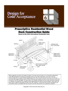
Prescriptive Residential Wood Deck Construction Guide
www.awc.org3. Maximum allowable overhang cannot exceed L/4 or ¼ of actual main span. Assumes cantilever length/180 deflection with 220 lb point load (See Figure 1A and Figure 2). 4. Incising assumed for Douglas Fir-Larch, Hem-Fir, and Spruce-Pine-Fir. 5. Design values based on northern species with no incising assumed. 6. Ledger shall be a minimum of 2x8 ...

2015 National Design Specification - AWC
www.awc.orgNDS-1991 with an approval date of October 16, 1992. In 2010, AWC was separately incorporated, re-chartered, and accredited by ANSI as a standards developing organization. The current edition of the Standard is designated ANSI/AWC NDS-2015 with an approval date of September 30, 2014. In developing the provisions of this Specification,
MAT100: The Basics of Wood Frame Construction
www.awc.orgone comprehensive program for building officials on wood frame construction basics. In each module, learning outcomes will be further refined respectively. MAT 100 learning outcomes (see slide). 5 MAT100: Learning Outcomes 3. Floor, roof/ceiling, wall framing 4. Wall bracing, introduction to Wood Frame Construction Manual 5. Fireblocking ...
Related documents
Chapter 11 SEISMIC DESIGN CRITERIA - Memphis
www.ce.memphis.eduand shear wall perimeters, interior openings, discontinuities, and reentrant corners. BOUNDARY MEMBERS: Portions along wall and di-aphragm edges strengthened by longitudinal and transverse re-inforcement. Boundary members include chords and drag struts at diaphragm and shear wall perimeters, interior openings, dis-continuities, and reentrant ...
Bearing Capacity of Rocks - IIT Kanpur
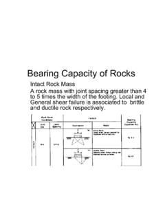
home.iitk.ac.inIn case of rock mass with favorable discontinuities, the net allowable bearing pressure may be estimated from: q a = q c * N j Where qWhere q c = average uniaxial compressive strength of rock coresaverage uniaxial compressive strength of rock cores N j = empirical coefficient depending on the spacing of the discontinuities 3+S/B 10 []1+300(δ/S) δ= thickness of …
4.5 Procedures for Diaphragms - Memphis
www.ce.memphis.edu4.5.1.4 OPENINGS AT SHEAR WALLS: Diaphragm openings immediately adjacent to the shear walls shall be less than 25% of the wall length for Life Safety and 15% of the wall length for Immediate Occupancy. Tier 2 Evaluation Procedure: The in-plane shear transfer demand at the wall shall be calculated. The adequacy of the diaphragm to transfer loads ...
Chapter 8 Foundation Design
www.wsdot.wa.govshear strength parameters compressibility parameters (including consolidation, shrink/swell potential, and elastic modulus) frost depth stress history (present and past vertical effective stresses) depth of seasonal moisture change unit weights geologic mapping including orientation and characteristics of rock discontinuities

Landslide Types and Processes - USGS
pubs.usgs.govSeparation occurs along discontinuities such as fractures, joints, and bedding planes, and movement occurs by free-fall, bouncing, and ... where shear stress continu-ously exceeds the strength of the material; and (3) progressive, where slopes are reaching ...

Chapter 9 Embankments - Washington State Department of ...
www.wsdot.wa.govshear strength parameters unit weights • • measurement) SPT PMT • • grain size distribution Atterberg Limits (available quantity and quality of borrow soil) • ... rock discontinuities • • unit weight relative density • shrink/swell/ degradation of soil ; and rock fill:

IS 1367-3 (2002): Technical Supply Conditions for Threaded ...
law.resource.orgdiscontinuities; Section 1 Bolts, screws and studs for general applications ( third revision) ... strength, may occur. When fasteners are to be used above or below the ambient temperature range it is the ... the head which reduces the shear area in the head as compared to the stress area in the thread such as countersunk, raised countersunk and ...

INTERNATIONAL ISO STANDARD 898-1
www.bsf-sh.comAnnex A (informative) Relationship between tensile strength and elongation after fracture.....54 Annex B (informative) Influence of ... the geometry of their heads reduces the shear area in the head compared to the stress area in the thread. ... Fasteners — Surface discontinuities — Part 1: Bolts, screws and studs for general requirements

CALCULATING WIND LOADS ON LOW-RISE STRUCTURES PER …
www.awc.orgShear wall overturning forces are resisted by the structure’s dead load and by supplemental hold down connections. Implicit in the assumption of a “box-like” structure is a roughly rectangular shape, relatively uniform distri-bution of shear resistance throughout the structure, and no significant structural discontinuities. In addition, the