Transcription of INTERIOR SHEAR WALLS - awc.org
1 8' tributary area to Wall C 10' tributary area to Wall C 16' 20' LMAX = 36' Wall C American WAmerican WAmerican WAmerican WAmerican Wood Councilood Councilood Councilood Councilood CouncilINTERIOR SHEAR WINTERIOR SHEAR WINTERIOR SHEAR WINTERIOR SHEAR WINTERIOR SHEAR WALLSALLSALLSALLSALLSA mericanAmericanAmericanAmericanAmericanF FFFF orest &orest &orest &orest &orest &PPPPP aperaperaperaperaperAssociationAssociati onAssociationAssociationAssociationDESIG N AID NDESIGN AID NDESIGN AID NDESIGN AID NDESIGN AID Nooooo. 8. 8. 8. 8. 82 DESIGN AID No. 8 AMERICAN WOOD COUNCILThe American Wood Council (AWC) is part of the wood products group of theAmerican Forest & Paper Association (AF&PA). AF&PA is the national tradeassociation of the forest, paper, and wood products industry, representing membercompanies engaged in growing, harvesting, and processing wood and wood fiber,manufacturing pulp, paper, and paperboard products from both virgin and recycledfiber, and producing engineered and traditional wood products.
2 For more informationsee every effort has been made to insure the accuracyof the information presented, and special effort has beenmade to assure that the information reflects the state-of-the-art, neither the American Forest & Paper Associationnor its members assume any responsibility for anyparticular design prepared from this publication. Thoseusing this document assume all liability from its 2007 American Forest & Paper Association, Wood Council1111 19th St., NW, Suite 800 Washington, DC SHEAR WINTERIOR SHEAR WINTERIOR SHEAR WINTERIOR SHEAR WINTERIOR SHEAR WALLSALLSALLSALLSALLSINTERIOR SHEAR WALLS3 AMERICAN FOREST & PAPER ASSOCIATIONWhat is meant by 2001 WFCM Section use of INTERIOR SHEAR WALLS to resist seismic loads?The last paragraph of WFCM Section states: Where INTERIOR SHEAR WALLS are used to resist seismicloads, the full height sheathing requirements shall bedetermined using the spacing of exterior SHEAR wall linesas the distance from the exterior SHEAR wall line to theinterior SHEAR wall line, and the spacing of INTERIOR shearwall lines as the sum of the distances to SHEAR wall lineson each side.
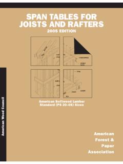
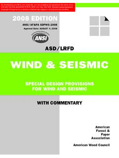
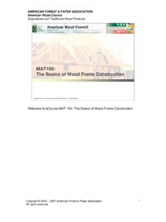
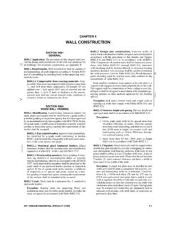
3 WFCM Table is the prescriptive table fordetermining segmented SHEAR wall sheathing requirementsfor resisting seismic loads. The table shows maximumspacing of exterior SHEAR wall lines (LMAX) and thecorresponding percent of full height sheathing values are based on tributary loads on shearwalls. So, for example, if a 24' building has no interiorshear WALLS , the underlying calculation is based on 12' oftributary area seismic load being distributed to eachexterior SHEAR wall and LMAX = 24' as shown in Figure underlying assumption for WFCMT able is that tributary area (1/2 LMAX)seismic loads are distributed to eachexterior SHEAR wall. Wall A LMAX = 24' 12' tributary area to Wall A 12' tributary area to Wall B Wall B INTERIOR SHEAR WALLS usedto Resist Seismic Loadsper the WFCMIf a building has one INTERIOR SHEAR wall as shown inFigure 2, the underlying calculation for WFCM is based on tributary area seismic loads beingdistributed to the INTERIOR SHEAR wall as shown in Figure this case, LMAX = 36' would be used in WFCM to determine percent full height sheathing.
4 Wall B Wall A 8' tributary area to Wall C 10' tributary area to Wall C 16' 20' LMAX = 36' Wall C Figure underlying assumption for WFCMT able is that tributary area seismicloads are distributed to the INTERIOR document describes how INTERIOR SHEAR WALLS aredesigned to resist lateral loads. AF&PA s Wood FrameConstruction Manual (WFCM) for One- and Two-FamilyDwellings, 2001 Edition and Special Design Provisionsfor Wind and Seismic (Wind & Seismic), 2005 Edition,each provide design criteria for SHEAR WALLS . However,emphasis is on exterior SHEAR that design assumptions are different for windloads versus seismic loads. While wind loads act primarilyon the skin of the structure, seismic loads are developedinternally due to weight of materials and components inthe structure.
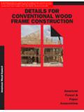
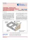
5 Therefore, certain provisions for interiorshear WALLS may only apply to seismic loads and not AID No. 8 AMERICAN WOOD COUNCILIf a building has multiple INTERIOR SHEAR WALLS as shownin Figure 3, the underlying calculation for WFCM is based on the tributary area seismic loads beingdistributed to INTERIOR SHEAR WALLS as shown in Figure 3. Inthis case, LMAX = 40' would be used in WFCM Table determine percent full height sheathing for Wall , if the distance between Wall A and Wall D is12', in order to determine percent full height sheathing forWall D, use LMAX = 16' + 12' = 28' in WFCM Table , if the distance between Wall B and Wall E is12', in order to determine percent full height sheathing forWall E, use LMAX = 24' + 12' = 36' in WFCM Table SHEAR WALLS usedto Resist Wind Loads perthe WFCMfor wind or seismic motion parallel to ridge.
6 Design loadsshall be distributed to the various vertical elements of theseismic force-resisting system in the story underconsideration, based on the relative lateral stiffness of thevertical resisting elements and the diaphragm. However, the designer must ensure that an appropriateload path is provided to distribute loads from the roofdiaphragm into vertical SHEAR WALLS . When wind loads areperpendicular to the ridge, this is fairly straightforward andguidance from the section on distributing seismic loads tointerior SHEAR WALLS could be wind loads are parallel to the ridge, using aninterior SHEAR wall to resist wind loads is more difficult. Inorder to transfer diaphragm loads, a vertical shearwallwould need to extend past the ceiling to the roof SHEAR WALLS perthe Wind & SeismicStandardDoes the 2001 WFCM permit use of INTERIOR SHEAR wallsto resist wind loads?
7 The engineering chapter of the WFCM does permitinterior SHEAR WALLS to be designed to resist wind Section states: WALLS parallel to the applicable wind load or seismicmotion shall provide the required SHEAR resistance at eachlevel. The sum of the individual shearwall segment shearcapacities shall meet or exceed the sum of SHEAR loadscollected by horizontal diaphragms above. Total SHEAR loadsshall be calculated in accordance with Table for windor seismic motion perpendicular to ridge and Table the 2005 Wind & Seismic standard permit the useof INTERIOR SHEAR WALLS to resist lateral loads?The Wind & Seismic standard does permit INTERIOR shearwalls to be designed to resist lateral loads. Since the standarddoes not differentiate between external and internal shearwalls, it implicitly permits the use of INTERIOR SHEAR WALLS toresist wind or seismic loads.
8 As noted above, the designermust ensure that adequate load path is provided to distributeloads from the roof diaphragm into vertical SHEAR assumption for WFCM is that tributary area seismic loadsare distributed to each INTERIOR SHEAR wall. Wall A Wall E Wall D Wall B 16' 8' tributary area to Wall C 12' tributary area to Wall C Wall C 24' LMAX-Wall C = 40' 12' 12' AF&PA American FAmerican FAmerican FAmerican FAmerican Forest & Porest & Porest & Porest & Porest & Paper Associationaper Associationaper Associationaper Associationaper AssociationAmerican WAmerican WAmerican WAmerican WAmerican Wood Councilood Councilood Councilood Councilood Council1111 19th S1111 19th S1111 19th S1111 19th S1111 19th Streetreetreetreetreet, NWt, NWt, NWt, NWt, NWSuitSuitSuitSuitSuite 800e 800e 800e 800e 800 WWWWW ashingtashingtashingtashingtashington, DC 20036on, DC 20036on, DC 20036on, DC 20036on, DC 20036 Phone: 202-463-4 Phone: 202-463-4 Phone: 202-463-4 Phone: 202-463-4 Phone: 202-463-4777771111133333 FFFFFax: 202-463-2ax: 202-463-2ax: 202-463-2ax.
9 202-463-2ax.