Transcription of Rigid Body Equilibrium
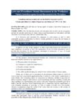
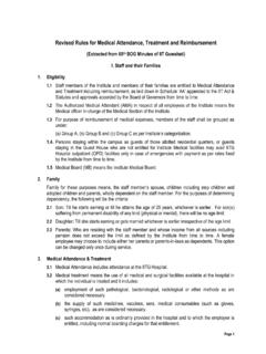
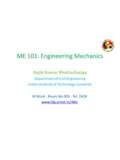
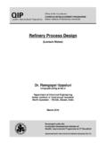
1 Rigid Body EquilibriumSupport ReactionsPrevention ofTranslation orRotation of a bodyRestraints1ME101 -Division IIIK austubh DasguptaRigid Body EquilibriumVarious Supports2-D Force Systems2ME101 -Division IIIK austubh DasguptaRigid Body EquilibriumVarious Supports3-D Force Systems3ME101 -Division IIIK austubh DasguptaRigid BodyEquilibriumCategories in 2-D4ME101 -Division IIIK austubh DasguptaRigid BodyEquilibriumCategories in 3-D5ME101 -Division IIIK austubh Dasgupta For all forces and moments acting on a two-dimensional structure,OzyxzMMMMF 00 Equations of Equilibrium become 000 AyxMFFwhere A is any point in the plane of the structure. The 3 equations can be solved for no more than 3 unknowns. The 3 equations can not be augmented with additional equations, but they can be replaced 000 BAxMMFE quilibrium of a Rigid Body in Two Dimensions6ME101 -Division IIIK austubh Dasgupta More unknowns than equations: Statically Indeterminate Fewer unknowns than equations, partially constrained Equal number unknowns and equations but improperly constrainedStatically Indeterminate Reactions7ME101 -Division IIIK austubh DasguptaA man raises a 10 kg joist, of length 4 m, by pulling on a the tensionin the ropeand the reaction at : Create a free-body diagramof the joist.
2 -The joist is a 3 force bodyacted upon by the rope, its weight, and the reaction at A. The three forcesmust be concurrentfor static Equilibrium . -Reaction Rmust pass through the intersection of the lines of action of the weight and rope forces. -Determine the direction of the reaction force R. Utilize a force triangleto determine the magnitude of the reaction force Body Equilibrium : Example8ME101 -Division IIIK austubh Dasgupta Create a free-body diagramof the joist Determine the direction of the reaction force R )2045cot(m AECEBDBFCECDBDAFAECDABAF Rigid Body Equilibrium : Example9ME101 -Division IIIK austubh Dasgupta Determine the magnitude of the reaction forceR. RTN RTRigid Body Equilibrium : Example10ME101 -Division IIIK austubh DasguptaEngineering Structure Any connected system of membersto transferthe loadsand safely withstandthem11ME101 -Division IIIK austubh DasguptaME101 -Division IIIS tructural AnalysisStructural Analysis ME101 Trusses/Frames/Machines/Beams/Cables Statically Determinate StructuresTo determine the internal forces in the structure, dismember the structure and analyze separate free body diagrams of individual members or combination of DasguptaStructural Analysis :: Plane TrussME101 -Division III13 Kaustubh DasguptaStructural Analysis :: Plane TrussME101 -Division III14 Kaustubh DasguptaStructural Analysis: Plane TrussTruss.
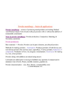
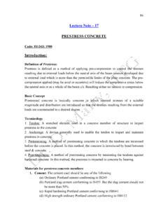
3 A framework composed of members joined at their ends to form a Rigid structure Joints (Connections): Welded, Riveted, Bolted, PinnedPlane Truss: Members lie in a single plane15ME101 -Division IIIK austubh DasguptaStructural Analysis: Plane TrussSimple TrussesBasic Element of a Plane Truss is the Triangle Three bars joined by pins at their ends Rigid Frame Non-collapsible and deformation of members due to induced internal strains is negligible Four or more bars polygon Non- Rigid FrameHow to make it Rigid or stable? Structures built from basic triangles Simple Trussesby forming more triangles!16ME101 -Division IIIK austubh DasguptaStructural Analysis: Plane TrussBasic Assumptions in Truss Analysis All members are two-force members Weight of the members is small comparedwith the force it supports (weight may be considered at joints).
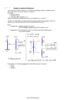
4 No effect of bending on members even if weight is considered External forces are applied at the pin connections Welded or riveted connections Pin Joint if the member centerlines are concurrent at the jointCommon Practice in Large Trusses-Roller/Rocker at one end. Why?-to accommodate deformations due to temperature changes and applied it will be a statically indeterminate truss17ME101 -Division IIIK austubh DasguptaStructural Analysis: Plane TrussTruss Analysis: Method of Joints Finding forces in membersMethod of Joints: Conditions of Equilibrium are satisfied for the forces at each joint Equilibrium of concurrent forces at each joint only two independent Equilibrium equations are involvedSteps of Free Body Diagram of external reactions by applying Equilibrium equations to the whole the force analysis of the remainder of the truss by Method of Joints18ME101 -Division IIIK austubh DasguptaStructural Analysis.
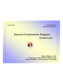
5 Plane TrussMethod of Joints Start with any joint where at least one known load exists and where not more than two unknown forces are of Joint A and members AB and AF: Magnitude of forces denoted as AB& AF-Tension indicated by an arrow away from the pin-Compression indicated by an arrow toward the pinMagnitude of AF from Magnitude of AB fromAnalyze joints F, B, C, E, & D in that order to complete the analysis19ME101 -Division IIIK austubh DasguptaKaustubh DasguptaStructural Analysis: Plane TrussMethod of Joints Negative force if assumed sense is incorrectZero Force MemberCheck EquilibriumShow forces on members20ME101 -Division IIIM ethod of Joints: ExampleDetermine the force in each member of the loaded truss by the method of joints21ME101 -Division IIIK austubh DasguptaMethod of Joints: ExampleKaustubh Dasgupta22ME101 -Division IIIFree Body DiagramMethod of Joints: Example Joint AKaustubh Dasgupta23ME101 -Division IIIM ethod of Joints: Example Joint B24ME101 -Division IIIK austubh DasguptaMethod of Joints: Example Joint C25ME101 -Division IIIK austubh DasguptaMethod of Joints: Example Joint E26ME101 -Division IIIK austubh Dasgupta