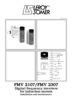
Transcription of Unidrive SP - Nidec Leroy-Somer
1 Unidrive SPQuick start commissioning guidePositioning SolutionPart number : 3773 en - / c23 Unidrive SP - POSITIONING SOLUTIONUNIDRIVE SP - POSITIONING SOLUTIONQ uick start commissioning guide3773 en - / cQuick start commissioning guide3773 en - / c 2 Leroy-Somer QUICK START COMMISSIONING GUIDE Unidrive SP Positioning solution 3773 en - / b Incorrect operational procedures may cause serious body injuries or materialdamages. This guide may be used only by qualified personnel able to complywith the safety precautions related to electronic drives. See the installation and thecommissioning manual that may be found on the CD ROM supplied together with thevariable speed drive. Page 2 Jeudi, 20. avril 2006 9:29 0923 Unidrive SP - POSITIONING SOLUTIONUNIDRIVE SP - POSITIONING SOLUTIONQ uick start commissioning guide3773 en - / cQuick start commissioning guide3773 en - / c 3 Leroy-Somer QUICK START COMMISSIONING GUIDE Unidrive SP Contents 3773 en - / b 1 - GENERAL INFORMATION.
2 4 - Absolute mode/relative mode .. - Origin cycling on reference sensor .. - 2 - SM MODULE - Access to terminal blocks .. - Module installation ..5 3 - CONNECTIONS ..6 - Power connection .. - Encoder connection .. - Control connection ..8 4 - PARAMETER-SETTING ..10 - Display and keyboard .. - Selection and modification of a parameter .. - Access level .. - Modification of the operating - Return to positioning factory settings ..12 5 - COMMISSIONING ..136 - - DIAGNOSTICS ..21 Page 3 Jeudi, 20. avril 2006 9:29 0945 Unidrive SP - POSITIONING SOLUTIONUNIDRIVE SP - POSITIONING SOLUTIONQ uick start commissioning guide3773 en - / cQuick start commissioning guide3773 en - / c 4 Leroy-Somer QUICK START COMMISSIONING GUIDE Unidrive SP Positioning solution 3773 en - / b 1 - GENERAL INFORMATION The SP POS solution offers all with positioning application comprises :- a Unidrive SP variable speed drive,- a SM-POS module,- a SM-I/O module.
3 Note : If the Positioning solution is managed by a field bus (use of a SM-Field bus module instead of a SM-I/O module), see the complete manual, that may be created from the CD Romsupplied together with the variable speed drive. - Absolute mode/relative mode The positioning mode depends on the origin mode :Relative mode : - Origin cycling on reference sensor In standard version, a reference sensor must be mounted onto the installation and it will allowthe location of the origin position. - Stops Two software stops allow the limitation of the travel of the mobile to be positioned (used in ab-solute mode). For safety, end of travel switches must be installed between the software stopsand the mechanical system limits. Softwarestop 1P1 = XSoftwarestop 2P2 = Y0P3P1P2P3 = -ZOriginP1 = + XP2 = P1 + X0P1P2P4P3P3 = P2 + YP4 = P3 - Z Page 4 Jeudi, 20.
4 Avril 2006 9:29 0945 Unidrive SP - POSITIONING SOLUTIONUNIDRIVE SP - POSITIONING SOLUTIONQ uick start commissioning guide3773 en - / cQuick start commissioning guide3773 en - / c 5 Leroy-Somer QUICK START COMMISSIONING GUIDE Unidrive SP Positioning solution 3773 en - / b 2 - SM MODULE INSTALLATION The drive must be powered down. - Access to terminal blocks Size 1 Size 2 Size 3 or 4 CAUTION :Dismantle the internal RFI filter on a driveof size 3 or 4, powered by a mains supplywithout earthing (IT supply). If an externalRFI filter is used or an additional motorearth protection is used, it is not necessa-ry to remove the internal +DCBR22232425262728293031L1L2L3 UVW567891011252627282930314142 WVUL348V-DC+DCBR48V-DC+DCBR - Module installation - Install the SM-POS module in the lowestpossible location and press gently on the mo-dule until hearing a Then, proceed in the same way as regardsthe SM-I/O module in the middle If necessary, to dismantle a module, pressat the same time on both sides of the moduleand remove it.
5 22232425262728293031L1L2L3 UVWNot usedSM-I/OSM-POS Page 5 Jeudi, 20. avril 2006 9:29 0967 Unidrive SP - POSITIONING SOLUTIONUNIDRIVE SP - POSITIONING SOLUTIONQ uick start commissioning guide3773 en - / cQuick start commissioning guide3773 en - / c 6 Leroy-Somer QUICK START COMMISSIONING GUIDE Unidrive SP Positioning solution 3773 en - / b 3 - - Power connection Power supply for an AC 3-phase mains supply, applicable to the safety standard EN 954-1 Categ. B or 1. CAUTION :Before making the power connection, be aware of the location of the drive terminalblocks (different depending on drive size). If necessary, see section D of the manual sup-plied together with the controlpower supply3-phase mains supply200 - 240V 10 %380 - 480V 10 %500 - 575V 10 %500 - 690V 10 %SB1 FRAU SB2 PERFI filteroptionLine chokeoptionMC chokeoptionU VWMotoror(1) Unidrive SP When we use a brake resistor, it is necessary to set = FAST.
6 The protection by thermal relays of the optional external brake resistor is necessary. In this case, set and to resistor option(2) FRRFDC1(1) For size 1, a single terminal block (48V, -DC, +DC, BR). Connect the resistor between +DC and BR.(2) The thermal relay is not necessary for the resistors that may be integrated into the heater.(3) Terminal 31 : safety input/disabling. When this input is open, it disables the drive. Its conception is so that even in case of failure of one or many components, the absence of the torque on the motor shaft should be guaranteed with a very high level of integrity. For detailed instructions or for schemas according to the safety standard EN 954-1 category 2 or 3, see section D of the installation and commissioning manual that is located on the CD (3)+DCBRL1 L2L3 UVWF Brake power supplyKFAcc.
7 To application Page 6 Jeudi, 20. avril 2006 9:29 0967 Unidrive SP - POSITIONING SOLUTIONUNIDRIVE SP - POSITIONING SOLUTIONQ uick start commissioning guide3773 en - / cQuick start commissioning guide3773 en - / c 7 Leroy-Somer QUICK START COMMISSIONING GUIDE Unidrive SP Positioning solution 3773 en - / b - Encoder connection HD 15 drive and modesIncrementalSincosSincos - hiperface linkSincos - EndAt or SSI linkEndAt or SSI 1 : B or FCosCosCos- : A or F2 : B\ or F\CosRefCosRefCosRef- : A\or F\3 : A or D or RSinSinSin- : B or D or R4 : A\ or D\ or R\SinRefSinRefSinRef- : B\ or D\ or R\5C or O or Z-DataDataData6C\ or O\ or Z\- Data\Data\Data\7 : U----8 : U\----9 : V----10 : V\----11 : W--ClockClock12 : W\--Clock\Clock\13+5V or +8V or +15V140V15 Motor thermal probe CAUTION.
8 Internal link pin 15 and terminal 8 of the drive. Connect one or 15pinsDriveconnectorUnidrive SPExample : encoder in quadratureMotorencoderconnectorStrip the side of the cablein contact with the earthing collarShielding supportto be screwed onthe drive thermal probe-UU\VV\WW\AC or O orZC\ or O\ or Z\A\BB\+5V or +8V or + +5V or +8V or +12 VABC or O or ZA\B\C\ or O\ or Z\--Shielding (*)-DesignationL126272845678910112930314 142L2L3 UVW22232425161151015(*) Depending on the encoder supplier,the shielding may be different from that indicated in the there is no shielding terminalavailable, connect the shielding to 360 at the connector (*) Page 7 Jeudi, 20. avril 2006 9:29 0989 Unidrive SP - POSITIONING SOLUTIONUNIDRIVE SP - POSITIONING SOLUTIONQ uick start commissioning guide3773 en - / cQuick start commissioning guide3773 en - / c 8 Leroy-Somer QUICK START COMMISSIONING GUIDE Unidrive SP Positioning solution 3773 en - / b - Control connection124142511910821222324252627282 930314637 Upper controlterminalblockUNIDRIVESPL owercontrolterminalblockRelayterminalblo ckCommon 0 VExternal power supply +24 VCommon 0 VCommon 0 VCommon 0 VCommon 0 VDigital 0V To terminal 22 of the driveCommon 0V+24 VMotorprobeOK +I-Run/StopOrigin cycling sensorIvalSafety input/enablingFault relayRelay(eventuallyfor the brake)12212223591084637PL2 terminal block SM-I/OmodulePL1terminalblock+24V1112xx: inputLegend:: outputCAUTION.
9 If the motor probe is connectedto pin15 of the HD-15 connector(see encoder connection), terminal8 of the drive is no longer available. In factory settings, Unidrive SP is set in positive association of a drive with a different command logic may cause the sudden start of the motor. Page 8 Jeudi, 20. avril 2006 9:29 0989 Unidrive SP - POSITIONING SOLUTIONUNIDRIVE SP - POSITIONING SOLUTIONQ uick start commissioning guide3773 en - / cQuick start commissioning guide3773 en - / c 9 Leroy-Somer QUICK START COMMISSIONING GUIDE Unidrive SP Positioning solution 3773 en - / b 2 I 1 to I 4 inputs (SM-I/O) 346 They are used for the selection of an encoded or direct mode position 7 I + and I - inputs (SM-I/O) 8 They control the manual movement of the mobile, at a low speed 24 OK ref.
10 OutputThe origin cycling has been correctly effected. It allows the authorisation of the positioning commands. 25 O val output The mobile reached the required position 26 I o inputIt gives the command to proceed to an origin cycling 27 Reference cycling sensor inputSensor necessary to set the positioning origin in absolute mode 28 Run/Stop inputIt gives the Run or Stop command 29 I val inputIt validates the position command in encoded modeAs the position selection is made by I 1 - I 4 inputs, I val allows the authorisation of the movement once the selection is ended 41 Relay output 42 When the contact is open, the drive is powered down or stopped Page 9 Jeudi, 20. avril 2006 9:29 091011 Unidrive SP - POSITIONING SOLUTIONUNIDRIVE SP - POSITIONING SOLUTIONQ uick start commissioning guide3773 en - / cQuick start commissioning guide3773 en - / c 10 Leroy-Somer QUICK START COMMISSIONING GUIDE Unidrive SP Positioning solution 3773 en - / b 4 - - Display and keyboard LED display Ref.