Transcription of Chapter 12 – Plate Bending Elements - Memphis
1 Chapter 12 Plate Bending ElementsLearning Objectives To introduce basic concepts of Plate Bending . To derive a common Plate Bending element stiffness matrix. To present some Plate element numerical comparisons. To demonstrate some computer solutions for Plate Bending 12 Plate Bending ElementsLearning Objectives To introduce basic concepts of Plate Bending . To derive a common Plate Bending element stiffness matrix. To present some Plate element numerical comparisons. To demonstrate some computer solutions for Plate Bending 7/8117 Chapter 12 - Plate Bending Elements1/34 Chapter 12 Plate Bending ElementsLearning Objectives To introduce basic concepts of Plate Bending . To derive a common Plate Bending element stiffness matrix. To present some Plate element numerical comparisons.
2 To demonstrate some computer solutions for Plate Bending of the Plate Bending ElementIntroductionIn this section we will begin by describing elementary concepts of Plate Bending behavior and theory. The Plate element is one of the more important structural Elements and is used to model and analyze such structures as pressure vessels, chimney stacks, and automobile parts. A large number of Plate Bending element formulations exist that would require lengthy Chapter to cover. CIVL 7/8117 Chapter 12 - Plate Bending Elements2/34 Development of the Plate Bending ElementIntroductionThe purpose in this Chapter is to present the derivation of the stiffness matrix for one of the most common Plate Bending finite Elements and then to compare solutions to some classical problems for a variety of Bending Elements in the literature.
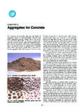
3 Development of the Plate Bending ElementBasic Concepts of Plate Bending A Plate can be considered the two-dimensional extension of a beam in simple Bending . Both plates and beams support loads transverse or perpendicular to their plane and through Bending action. A Plate is flat (if it were curved, it would be a shell). A beam has a single Bending moment resistance, while a Plate resists Bending about two axes and has a twisting will consider the classical thin- Plate theory or Kirchhoff Plate 7/8117 Chapter 12 - Plate Bending Elements3/34 Development of the Plate Bending ElementBasic Behavior of Geometry and Deformation Consider the thin Plate in the x-yplane of thickness tmeasured in the zdirection shown in the figure below:The Plate surfaces are at z = t/2, and its midsurface is at z = Plate thickness is much smaller than its inplane dimensionsband c(that is, t << bor c)Development of the Plate Bending ElementBasic Behavior of Geometry and Deformation Consider the thin Plate in the x-yplane of thickness tmeasured in the zdirection shown in the figure below.
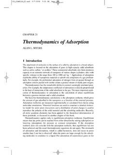
4 If tis more than about one-tenth the span of the Plate , then transverse shear deformation must be accounted for and the Plate is then said to be 7/8117 Chapter 12 - Plate Bending Elements4/34 Development of the Plate Bending ElementBasic Behavior of Geometry and Deformation Consider the thin Plate in the x-yplane of thickness tmeasured in the zdirection shown in the figure below:2. The deflection w is much less than the thickness t(than is, w/t << 1).Development of the Plate Bending ElementKirchhoff Assumptions Consider the differential slice cut from the Plate by planes perpendicular to the xaxis as show in the figure below:Loading qcauses the Plate to deform laterally or upward in the zdirection and, the defection wof point Pis assumed to be a function of xand yonly; that is w = w(x, y)and the Plate does not stretch in the 7/8117 Chapter 12 - Plate Bending Elements5/34 Development of the Plate Bending ElementKirchhoff Assumptions Consider the differential slice cut from the Plate by planes perpendicular to the xaxis as show in the figure below:The line a-bdrawn perpendicular to the Plate surface before loading remains perpendicular to the surface after of the Plate Bending ElementKirchhoff Assumptions Consider the differential slice cut from the Plate by planes perpendicular to the xaxis as show in the figure below:1.
5 Normals remain normal. This implies that transverse shears strains yz= 0 and xz= 0. However xydoes not equal to zero. Right angles in the plane of the Plate may not remain right angles after loading. The Plate may twist in the 7/8117 Chapter 12 - Plate Bending Elements6/34 Development of the Plate Bending ElementKirchhoff Assumptions Consider the differential slice cut from the Plate by planes perpendicular to the xaxis as show in the figure below:2. Thickness changes can be neglected and normals undergo no extension. This means that z= of the Plate Bending ElementKirchhoff Assumptions Consider the differential slice cut from the Plate by planes perpendicular to the xaxis as show in the figure below:3. Normal stress zhas no effect on in-plane strains xand yin the stress-strain equations and is considered 7/8117 Chapter 12 - Plate Bending Elements7/34 Development of the Plate Bending ElementKirchhoff Assumptions Consider the differential slice cut from the Plate by planes perpendicular to the xaxis as show in the figure below:4.
6 Membrane or in-plane forces are neglected here, and the plane stress resistance can be superimposed later (that is, the constant-strain triangle behavior of Chapter 6 can be superimposed with the basic Plate Bending element resistance). Development of the Plate Bending ElementKirchhoff Assumptions Consider the differential slice cut from the Plate by planes perpendicular to the xaxis as show in the figure below:4. Therefore, the in-plane deflections in the xand ydirections at the midsurface, z= 0, are assumed to be zero; u(x, y,0)= 0 and v(x, y,0) = 7/8117 Chapter 12 - Plate Bending Elements8/34 Development of the Plate Bending ElementKirchhoff Assumptions Based on Kirchhoff assumptions, at any point Pthe displacement in the xdirection due to a small rotation is: At the same point, the displacement in the ydirection is: wvz zy wuz zx The curvatures of the Plate are then given as the rate of change of the angular displacements of the normals and defined as: 222222xyxyww wxyxy Development of the Plate Bending ElementKirchhoff Assumptions Using the definitions for in-plane strains, along with the curvature relationships, the in-plane strain/displacement equations are: 222222xy xyww wzz zxyxy The first of the above equations is used in beam theory.
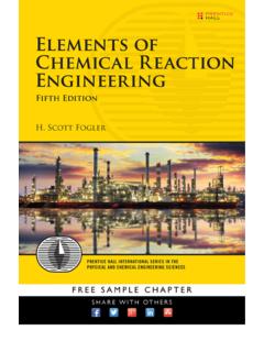
7 The remaining two equations are new to Plate 7/8117 Chapter 12 - Plate Bending Elements9/34 Development of the Plate Bending ElementStress/Strain Relationship Based on the third Kirchhoff assumption, the plane stress equations that relate in-plane stresses to in-plane strains for an isotropic material are: 21xxyE 21yyxE xyxyG Similar to the stress variation in a beam, the stresses vary linearly in the zdirection from the midsurface of the Plate . Development of the Plate Bending ElementStress/Strain Relationship The in-plane normal stresses and shear stress are shown acting on the edges of the Plate shown in figure below:CIVL 7/8117 Chapter 12 - Plate Bending Elements10/34 The transverse shear stresses yzand xzare also present, even though transverse shear deformation is neglected. These stresses vary quadratically through the Plate of the Plate Bending ElementStress/Strain Relationship The in-plane normal stresses and shear stress are shown acting on the edges of the Plate shown in figure below:Development of the Plate Bending ElementStress/Strain Relationship The Bending moments acting along the edge of the Plate can be related to the stresses by: /2/2/2/2/2/2tt txxyyxyxytt tMz dzMz dzMz dz CIVL 7/8117 Chapter 12 - Plate Bending Elements11/34 Development of the Plate Bending ElementStress/Strain Relationship Substituting strains for stresses gives: /22/21txxytEMzdz /22/21tyyxtEMzdz /2/2txyxytMzGdz Development of the Plate Bending ElementStress/Strain Relationship Using the strain/curvature relationships, the moment expression become.
8 XxyMD yyxMD (1)2xyxyDM where D= Et3/[12(1 - 2)] is called the Bending rigidity of the maximum magnitude of the normal stress on each edge of the Plate are located at the top or bottom at z = t/2. For example, it can be shown that: 26xxMt CIVL 7/8117 Chapter 12 - Plate Bending Elements12/34 Development of the Plate Bending ElementStress/Strain Relationship The equilibrium equations for Plate Bending are important in selecting the element displacement fields. The governing differential equations are: 0yxQQqxy 0xyxxMMQxy 0yxyyMMQyxwhere qis the transverse distributed loading and Qxand Qyare the transverse shear line of the Plate Bending ElementStress/Strain Relationship The transverse distributed loading qand the transverse shear line loads Qxand Qyare the shown below: 0yxQQqxy 0xyxxMMQxy 0yxyyMMQyxCIVL 7/8117 Chapter 12 - Plate Bending Elements13/34 Development of the Plate Bending ElementStress/Strain Relationship Substituting the moment/curvature expressions in the last two differential equations list above, solving for Qxand Qy, and substituting the results into the first equation listed above, the governing partial differential equation for isotropic, thin- Plate Bending may be derived as.
9 44442242wwwDqxxyywhere the solution to the thin- Plate Bending is a function of the transverse displacement w. Development of the Plate Bending ElementStress/Strain Relationship Substituting the moment/curvature expressions in the last two differential equations list above, solving for Qxand Qy, and substituting the results into the first equation listed above, the governing partial differential equation for isotropic, thin- Plate Bending may be derived as: 44442242wwwDqxxyyIf we neglect the differentiation with respect to the ydirection, the above equation simplifies to the equation for a beam and the flexural rigidity Dof the Plate reduces to the EIof the beam when the Poisson effect is set to 7/8117 Chapter 12 - Plate Bending Elements14/34 Development of the Plate Bending ElementPotential Energy of a PlateThe total potential energy of a Plate is given as.
10 12xxyyxyxyVUdV The potential energy can be expressed in terms of moments and curvatures as: 12xxyyxyxyAUMMMdA Development of the Plate Bending ElementDerivation of a Plate Bending Element StiffnessNumerous finite Elements for plates Bending have been developed over the years, references cite 88 different this section, we will introduce the basic12-degree-of-freedom rectangular element shown formulation will be developed consistently with the stiffness matrix and equations for the bar, beam, plane stress/strain Elements of previous chapters. CIVL 7/8117 Chapter 12 - Plate Bending Elements15/34 Development of the Plate Bending ElementStep 1 - Discretize and Select Element Types Consider the 12-degree-of-freedom Plate element shown in the figure below. Each node has 3 degrees of freedom a transverse displacement win the zdirection, a rotation xabout the xaxis, and a rotation yabout the yaxis.